1
Table 4-2 OMR MB/MA Value at Reset (Continued)
OMR MB =
Flash Secured
OMR MA =
Chip Operating Mode
EXTBOOT Pin
State2,3
1
1
Mode 1 – External Boot; Flash Memory is not secured; EMI configuration is
determined by the state of the EMI_MODE pin
1. Information in shaded areas not applicable to 56F8345/56F8145.
2. This bit is only configured at reset. If the Flash secured state changes, this will not be reflected in MB until the next reset.
3. Changing MB in software will not affect Flash memory security.
After reset, the OMR MA bit can be changed and will have an effect on the P-space memory map, as shown
in Table 4-3. Changing the OMR MB bit will have no effect.
Table 4-3 Changing OMR MA Value During Normal Operation
OMR MA
Chip Operating Mode
0
Use internal P-space memory map configuration
Use external P-space memory map configuration – If MB = 0 at reset, changing this bit has no effect.
11
1. Setting this bit can cause unpredictable results and is not recommended, since the EMI is not functional in this package.
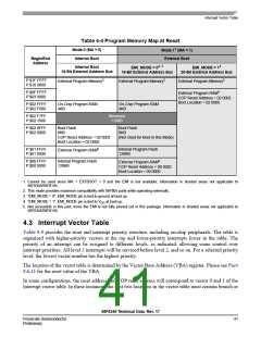
Table 4-4 shows the memory map options of the 56F8345/56F8145. The two right columns cannot be
used, since the EMI pins are not provided in the package; therefore, only the Mode 0 column is relevant.
Note: Program RAM is NOT available on the 56F8145 device.
56F8345 Technical Data, Rev. 17
40
Freescale Semiconductor
Preliminary

 FREESCALE [ Freescale ]