áç
ST16C1550/51
2.97V TO 5.5V UART WITH 16-BYTE FIFO
REV. 4.2.0
FCR[2]: TX FIFO Reset
This bit is only active when FCR bit-0 is a ‘1’.
• Logic 0 = No transmit FIFO reset (default).
• Logic 1 = Reset the transmit FIFO pointers and FIFO level counter logic (the transmit shift register is not
cleared or altered). This bit will return to a logic 0 after resetting the FIFO.
FCR[3]: DMA Mode Select
Controls the behavior of the TXRDY# and RXRDY# pins. See DMA operation section for details.
• Logic 0 = Normal Operation (default).
• Logic 1 = DMA Mode.
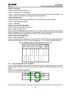
FCR[5:4]: Transmit FIFO Trigger Select
These 2 bits are only active when IER bit-5 is a ‘1’.
(logic 0 = default, TX trigger level = 1)
These 2 bits set the trigger level for the transmit FIFO. The UART will issue a transmit interrupt when the
number of characters in the FIFO falls below the selected trigger level, or when it gets empty in case that the
FIFO did not get filled over the trigger level on last re-load. Table 6 shows the selections.
FCR[7:6]: Receive FIFO Trigger Select
(logic 0 = default, RX trigger level =1)
These 2 bits are used to set the trigger level for the receive FIFO. The UART will issue a receive interrupt when
the number of the characters in the FIFO crosses the trigger level. Table 6 shows the complete selections.
TABLE 6: TRANSMIT AND RECEIVE FIFO TRIGGER LEVEL SELECTION
RECEIVE TRANSMIT
FCR
BIT-7
FCR
BIT-6
FCR
BIT-5
FCR
BIT-4
TRIGGER
LEVEL
TRIGGER
LEVEL
0
0
1
1
0
1
0
1
1
4
8
14
0
0
1
1
0
1
0
1
1
4
8
14
4.6
Line Control Register (LCR) - Read/Write
The Line Control Register is used to specify the asynchronous data communication format. The word or
character length, the number of stop bits, and the parity are selected by writing the appropriate bits in this
register.
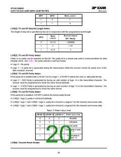
LCR[1:0]: TX and RX Word Length Select
These two bits specify the word length to be transmitted or received.
BIT-1
BIT-0
WORD LENGTH
5 (default)
6
0
0
0
1
19

 EXAR [ EXAR CORPORATION ]