ST16C1550/51
2.97V TO 5.5V UART WITH 16-BYTE FIFO
áç
REV. 4.2.0
BIT-1
BIT-0
WORD LENGTH
1
1
0
1
7
8
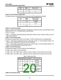
LCR[2]: TX and RX Stop-bit Length Select
The length of stop bit is specified by this bit in conjunction with the programmed word length.
STOP BIT LENGTH
(BIT TIME(S))
WORD
LENGTH
BIT-2
0
1
1
5,6,7,8
5
1 (default)
1-1/2
2
6,7,8
LCR[3]: TX and RX Parity Select
Parity or no parity can be selected via this bit. The parity bit is a simple way used in communications for data
integrity check. See Table 7 for parity selection summary below.
• Logic 0 = No parity.
• Logic 1 = A parity bit is generated during the transmission while the receiver checks for parity error of the
data character received.
LCR[4]: TX and RX Parity Select
If the parity bit is enabled with LCR bit-3 set to a logic 1, LCR BIT-4 selects the even or odd parity format.
• Logic 0 = ODD Parity is generated by forcing an odd number of logic 1’s in the transmitted character. The
receiver must be programmed to check the same format (default).
• Logic 1 = EVEN Parity is generated by forcing an even number of logic 1’s in the transmitted character. The
receiver must be programmed to check the same format.
LCR[5]: TX and RX Parity Select
If the parity bit is enabled, LCR BIT-5 selects the forced parity format.
• LCR[5] = logic 0, parity is not forced (default).
• LCR[5] = logic 1 and LCR[4] = logic 0, parity bit is forced to a logical 1 for the transmit and receive data.
• LCR[5] = logic 1 and LCR[4] = logic 1, parity bit is forced to a logical 0 for the transmit and receive data.
TABLE 7: PARITY SELECTION
LCR BIT-5 LCR BIT-4 LCR BIT-3
PARITY SELECTION
No parity
X
0
0
1
X
0
1
0
0
1
1
1
Odd parity
Even parity
Force parity to mark,
“1”
1
1
1
Forced parity to
space, “0”
LCR[6]: Transmit Break Enable
20

 EXAR [ EXAR CORPORATION ]