ST16C1550/51
2.97V TO 5.5V UART WITH 16-BYTE FIFO
áç
REV. 4.2.0
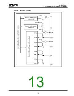
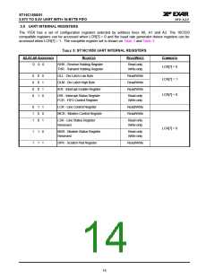
4.0 INTERNAL REGISTER DESCRIPTIONS
4.1
Receive Holding Register (RHR) - Read- Only
See “Receiver” on page 11.
4.2
Transmit Holding Register (THR) - Write-Only
See “Transmitter” on page 10.
4.3
Interrupt Enable Register (IER) - Read/Write
The Interrupt Enable Register (IER) masks the interrupts from receive data ready, transmit empty, line status
and modem status registers. These interrupts are reported in the Interrupt Status Register (ISR).
4.3.1
IER versus Receive FIFO Interrupt Mode Operation
When the receive FIFO (FCR BIT-0 = 1) and receive interrupts (IER BIT-0 = 1) are enabled, the RHR interrupts
(see ISR bits 2 and 3) status will reflect the following:
A.
B.
C.
The receive data available interrupts are issued to the host when the FIFO has reached the programmed
trigger level. It will be cleared when the FIFO drops below the programmed trigger level.
FIFO level will be reflected in the ISR register when the FIFO trigger level is reached. Both the ISR register
status bit and the interrupt will be cleared when the FIFO drops below the trigger level.
The receive data ready bit (LSR BIT-0) is set as soon as a character is transferred from the shift register to
the receive FIFO. It is reset when the FIFO is empty.
4.3.2
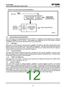
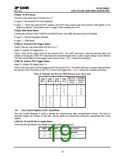
IER versus Receive/Transmit FIFO Polled Mode Operation
When FCR BIT-0 equals a logic 1 for FIFO enable; resetting IER bits 0-3 enables the ST16C155X in the FIFO
polled mode of operation. Since the receiver and transmitter have separate bits in the LSR either or both can
be used in the polled mode by selecting respective transmit or receive control bit(s).
A.
B.
C.
D.
E.
F.
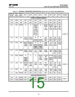
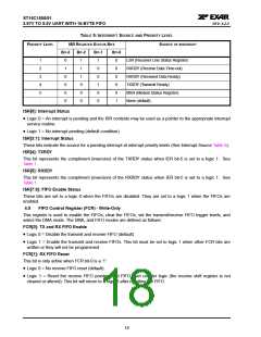
LSR BIT-0 indicates there is data in RHR or RX FIFO.
LSR BIT-1 indicates an overrun error has occurred and that data in the FIFO may not be valid.
LSR BIT 2-4 provides the type of receive data errors encountered for the data byte in RHR, if any.
LSR BIT-5 indicates THR is empty.
LSR BIT-6 indicates when both the transmit FIFO and TSR are empty.
LSR BIT-7 indicates a data error in at least one character in the RX FIFO.
IER[0]: RHR Interrupt Enable
The receive data ready interrupt will be issued when RHR has a data character in the non-FIFO mode or when
the receive FIFO has reached the programmed trigger level in the FIFO mode.
• Logic 0 = Disable the receive data ready interrupt (default).
• Logic 1 = Enable the receiver data ready interrupt.
IER[1]: THR Interrupt Enable
This bit enables the Transmit Ready interrupt which is issued whenever the THR is empty in the non-FIFO
mode or when data in the FIFO falls below the programmed trigger level in the FIFO mode. If the THR is empty
when this bit is enabled, an interrupt will be generated. Note that this interrupt does not behave in the same
manner as the industry standard 16C550. See “Interrupt Clearing:” on page 17.
• Logic 0 = Disable Transmit Ready interrupt (default).
• Logic 1 = Enable Transmit Ready interrupt.
16

 EXAR [ EXAR CORPORATION ]