ST16C1550/51
2.97V TO 5.5V UART WITH 16-BYTE FIFO
áç
REV. 4.2.0
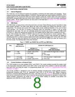
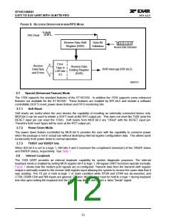
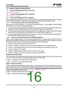
FIGURE 6. RECEIVER OPERATION IN NON-FIFO MODE
16X Clock
Receive Data Shift
Register (RSR)
Data Bit
Validation
Receive Data Characters
Error
Receive
Data Byte
and Errors
Receive Data
Holding Register
(RHR)
Tags in
LSR bits
4:2
RHR Interrupt (ISR bit-2)
RXFIFO1
2.7
Special (Enhanced Feature) Mode
The 155X supports the standard features of the ST16C550. In addition the 155X supports some enhanced
features not available for the ST16C550. These features are enabled by IER bit-5 and include a software
controllable (SOFT) reset, power down feature and FIFO monitoring bits.
2.7.1
Soft Reset
Soft resets are useful when the user desires the capability of resetting an externally connected device only.
MCR bit-2 can be used to initiate a SOFT reset at the RST output pin. This does not reset the 155X (only the
RESET input pin can reset the 155X). Soft resets from MCR bit-2 are “ORed” with the RESET input pin.
Therefore both reset types will be seen at the RST output pin.
2.7.2
Power Down Mode
The power down feature (controlled by MCR bit-7) provides the user with the capability to conserve power
when the package is not in actual use without destroying internal register configuration data. This allows quick
turnarounds from power down to normal operation.
2.7.3
TXRDY and RXRDY bits
When IER bit-5 is set to a logic 1, ISR bits 4 and 5 represent the compliment (inversion) of the TXRDY status
and RXRDY status, respectively. See Table 1.
2.8
Internal Loopback
The 155X UART provides an internal loopback capability for system diagnostic purposes. The internal
loopback mode is enabled by setting MCR register bit-4 to logic 1. All regular UART functions operate normally.
Figure 7 shows how the modem port signals are re-configured. Transmit data from the transmit shift register
output is internally routed to the receive shift register input allowing the system to receive the same data that it
was sending. The TX pin is held at logic 1 or mark condition while RTS# and DTR# are de-asserted, and
CTS#, DSR# CD# and RI# inputs are ignored. Caution: the RX input must be held to a logic 1 during loopback
test else upon exiting the loopback test the UART may detect and report a false “break” signal.
12

 EXAR [ EXAR CORPORATION ]