Epson Research and Development
Page 131
Vancouver Design Center
bits 1-0
MediaPlug Clock Source Select Bits [1:0]
These bits determine the source of the MediaPlug Clock for the MediaPlug Interface.
See Section 7.7, “MediaPlug Interface Timing” on page 123 for AC Timing.
Table 8-9: Video Clock Source Selection
MediaPlug Clock Source Select Bits
MediaPlug Clock Source
CLKI
00
01
10
11
BUSCLK
CLKI2
MCLK (see note)
Note
MCLK may be a previously divided down version of CLKI, CLKI2 or BUSCLK.
CPU To Memory Wait State Select Register
REG[01Eh]
RW
CPU to
Memory Wait Memory Wait
CPU to
n/a
n/a
n/a
n/a
n/a
n/a
State Select
Bit 1
State Select
Bit 0
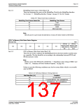
bits 1-0
CPU to Memory Wait State Select Bits [1:0]
These bits are used to optimize the handshaking between the host interface and the mem-
ory controller. The bits should be set according to the relationship between BCLK and
MCLK (memory clock).
Note
BCLK can be either BUSCLK or BUSCLK ÷ 2 depending on the setting of MD12 (see
Table 5-6:, “Summary of Power-On/Reset Options,” on pag e39).
Failure to meet the following conditions may lead to system failure which is recoverable
only by RESET.
Table 8-10: Minimum Memory Timing Selection
Wait State Bits [1:0]
Condition
no restrictions
00
01
10
11
2 x period (MCLK) - 4ns > period(BCLK)
period(MCLK) - 4ns > period(BCLK)
Reserved
Hardware Functional Specification
Issue Date: 01/02/06
S1D13506
X25B-A-001-10

 EPSON [ EPSON COMPANY ]