DA14580
FINAL
Bluetooth Low Energy 4.2 SoC
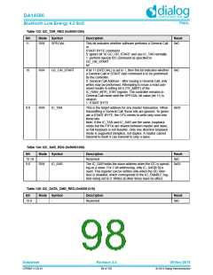
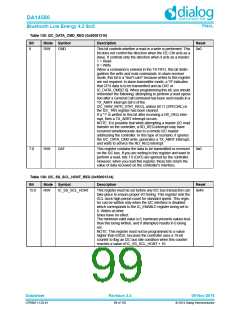
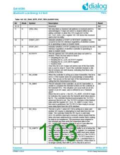
Table 135: I2C_DATA_CMD_REG (0x50001310)
Bit
Mode Symbol
R/W CMD
Description
Reset
0x0
8
This bit controls whether a read or a write is performed. This
bit does not control the direction when the I2C Ctrl acts as a
slave. It controls only the direction when it acts as a master.
1 = Read
0 = Write
When a command is entered in the TX FIFO, this bit distin-
guishes the write and read commands. In slave-receiver
mode, this bit is a "don't care" because writes to this register
are not required. In slave-transmitter mode, a "0" indicates
that CPU data is to be transmitted and as DAT or
IC_DATA_CMD[7:0]. When programming this bit, you should
remember the following: attempting to perform a read opera-
tion after a General Call command has been sent results in a
TX_ABRT interrupt (bit 6 of the
I2C_RAW_INTR_STAT_REG), unless bit 11 (SPECIAL) in
the I2C_TAR register has been cleared.
If a "1" is written to this bit after receiving a RD_REQ inter-
rupt, then a TX_ABRT interrupt occurs.
NOTE: It is possible that while attempting a master I2C read
transfer on the controller, a RD_REQ interrupt may have
occurred simultaneously due to a remote I2C master
addressing the controller. In this type of scenario, it ignores
the I2C_DATA_CMD write, generates a TX_ABRT interrupt,
and waits to service the RD_REQ interrupt
7:0
R/W
DAT
This register contains the data to be transmitted or received
on the I2C bus. If you are writing to this register and want to
perform a read, bits 7:0 (DAT) are ignored by the controller.
However, when you read this register, these bits return the
value of data received on the controller's interface.
0x0
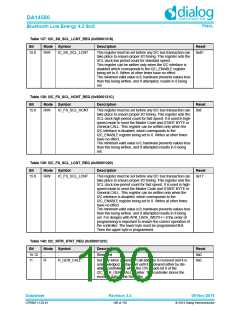
Table 136: I2C_SS_SCL_HCNT_REG (0x50001314)
Bit
Mode Symbol
R/W IC_SS_SCL_HCNT
Description
Reset
15:0
This register must be set before any I2C bus transaction can
take place to ensure proper I/O timing. This register sets the
SCL clock high-period count for standard speed. This regis-
ter can be written only when the I2C interface is disabled
which corresponds to the IC_ENABLE register being set to
0. Writes at other
0x48
times have no effect.
The minimum valid value is 6; hardware prevents values less
than this being written, and if attempted results in 6 being
set.
NOTE: This register must not be programmed to a value
higher than 65525, because the controller uses a 16-bit
counter to flag an I2C bus idle condition when this counter
reaches a value of IC_SS_SCL_HCNT + 10.
Datasheet
Revision 3.4
09-Nov-2016
CFR0011-120-01
99 of 155
© 2014 Dialog Semiconductor

 DIALOG [ Dialog Semiconductor ]