DA14580
FINAL
Bluetooth Low Energy 4.2 SoC
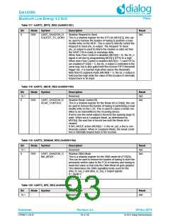
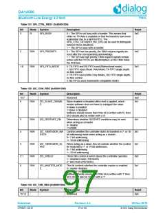
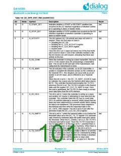
Table 131: SPI_CTRL_REG1 (0x50001208)
Bit
Mode Symbol
Description
Reset
3
R
SPI_BUSY
0 = The SPI is not busy with a transfer. This means that
either no TX-data is available or that the transfers have been
suspended due to a full RX-FIFO. The
0x0
SPIx_CTRL_REG0[SPI_INT_BIT] can be used to distinguish
between these situations.
1 = The SPI is busy with a transfer.
2
R/W
R/W
SPI_PRIORITY
0 = The SPI has low priority, the DMA request signals are
reset after the corresponding acknowledge.
1 = The SPI has high priority, DMA request signals remain
active until the FIFOS are filled/emptied, so the DMA holds
the AHB bus.
0x0
0x3
1:0
SPI_FIFO_MODE
0: TX-FIFO and RX-FIFO used (Bidirectional mode).
1: RX-FIFO used (Read Only Mode) TX-FIFO single depth,
no flow control
2: TX-FIFO used (Write Only Mode), RX-FIFO single depth,
no flow control
3: No FIFOs used (backwards compatible mode)
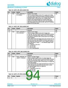
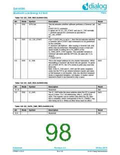
Table 132: I2C_CON_REG (0x50001300)
Bit
15:7
6
Mode Symbol
Description
Reset
0x0
-
-
Reserved
R/W
I2C_SLAVE_DISABL
E
Slave enabled or disabled after reset is applied, which
means software does not have to configure the slave.
0=slave is enabled
0x1
1=slave is disabled
Software should ensure that if this bit is written with '0', then
bit 0 should also be written with a '0'.
5
4
3
R/W
R/W
R/W
I2C_RESTART_EN
Determines whether RESTART conditions may be sent
when acting as a master
0= disable
0x1
1=enable
I2C_10BITADDR_MA Controls whether the controller starts its transfers in 7- or 10- 0x1
STER
bit addressing mode when acting as a master.
0= 7-bit addressing
1= 10-bit addressing
I2C_10BITADDR_SL
AVE
When acting as a slave, this bit controls whether the control- 0x1
ler responds to 7- or 10-bit addresses.
0= 7-bit addressing
1= 10-bit addressing
2:1
0
R/W
R/W
I2C_SPEED
These bits control at which speed the controller operates.
1= standard mode (100 kbit/s)
2= fast mode (400 kbit/s)
0x2
0x1
I2C_MASTER_MOD
E
This bit controls whether the controller master is enabled.
0= master disabled
1= master enabled
Software should ensure that if this bit is written with '1' then
bit 6 should also be written with a '1'.
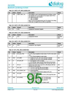
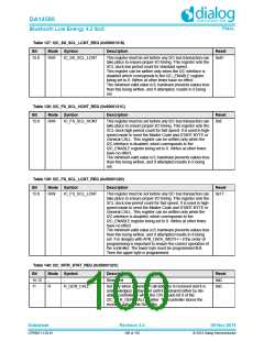
Table 133: I2C_TAR_REG (0x50001304)
Bit
Mode Symbol
Description
Reset
15:12
-
-
Reserved
0x0
Datasheet
Revision 3.4
09-Nov-2016
CFR0011-120-01
97 of 155
© 2014 Dialog Semiconductor

 DIALOG [ Dialog Semiconductor ]