DS3251/DS3252/DS3253/DS3254
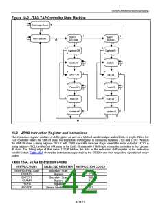
sequence for the instruction register. JTMS high during a rising edge on JTCLK puts the controller back into the
Test-Logic-Reset state.
Capture-IR. The Capture-IR state is used to load the shift register in the instruction register with a fixed value. This
value is loaded on the rising edge of JTCLK. If JTMS is high on the rising edge of JTCLK, the controller enters the
Exit1-IR state. If JTMS is low on the rising edge of JTCLK, the controller enters the Shift-IR state.
Shift-IR. In this state, the instruction register’s shift register is connected between JTDI and JTDO and shifts data
one stage for every rising edge of JTCLK toward the serial output. The parallel register and the test registers
remain at their previous states. A rising edge on JTCLK with JTMS high moves the controller to the Exit1-IR state.
A rising edge on JTCLK with JTMS low keeps the controller in the Shift-IR state, while moving data one stage
through the instruction shift register.
Exit1-IR. A rising edge on JTCLK with JTMS low puts the controller in the Pause-IR state. If JTMS is high on the
rising edge of JTCLK, the controller enters the Update-IR state and terminates the scanning process.
Pause-IR. Shifting of the instruction register is halted temporarily. With JTMS high, a rising edge on JTCLK puts
the controller in the Exit2-IR state. The controller remains in the Pause-IR state if JTMS is low during a rising edge
on JTCLK.
Exit2-IR. A rising edge on JTCLK with JTMS high puts the controller in the Update-IR state. The controller loops
back to the Shift-IR state if JTMS is low during a rising edge of JTCLK in this state.
Update-IR. The instruction shifted into the instruction shift register is latched into the parallel output on the falling
edge of JTCLK as the controller enters this state. Once latched, this instruction becomes the current instruction. A
rising edge on JTCLK with JTMS low puts the controller in the Run-Test-Idle state. With JTMS high, the controller
enters the Select-DR-Scan state.
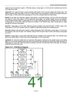
Figure 16-1. JTAG Block Diagram
BOUNDARY
SCAN
REGISTER
IDENTIFICATION
REGISTER
BYPASS
REGISTER
INSTRUCTION
REGISTER
SELECT
TEST ACCESS PORT
TRI-STATE
CONTROLLER
10k
10k
10k
JTDI
JTMS
JTCLK
JTDO
JTRST
41 of 71

 DALLAS [ DALLAS SEMICONDUCTOR ]