DS3251/DS3252/DS3253/DS3254
Table 17-C. Framer Interface Timing
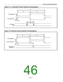
(VDD = 3.3V M5%, TA = -40°C to +85°C.) (Figure 17-1 and Figure 17-2)
PARAMETER
SYMBOL
CONDITIONS
MIN
TYP
MAX
UNITS
(Note 1)
(Note 2)
(Note 3)
22.4
29.1
19.3
RCLK/TCLK Clock Period
t1
ns
RCLK Duty Cycle
TCLK Duty Cycle
MCLK Duty Cycle
t2/t1, t3/t1
t2/t1, t3/t1
t2/t1, t3/t1
(Notes 4, 5)
45
30
30
50
55
70
70
%
%
%
(Note 5)
(Note 5)
TPOS/TDAT, TNEG to TCLK Setup
Time
t4
t5
t6
(Notes 5, 6)
(Notes 5, 6)
(Notes 4, 5, 7)
2
2
2
ns
ns
ns
TPOS/TDAT, TNEG Hold Time
RCLK to RPOS/RDAT, RNEG/RLCV,
and PRBS Value Change
6
RCLK Rise and Fall Time
TCLK Rise and Fall Time
t7
t8
(Notes 5, 8)
(Notes 5, 9)
3
5
5
ns
ns
Note 1:
Note 2:
Note 3:
Note 4:
Note 5:
Note 6:
DS3 mode.
E3 mode.
STS-1 mode.
Outputs loaded with 25pF, measured at 50% threshold.
Not tested during production test.
When TCINV = 0, TPOS/TDAT and TNEG are sampled on the rising edge of TCLK. When TCINV = 1, TPOS/TDAT and TNEG
are sampled on the falling edge of TCLK.
Note 7:
When RCINV = 0, RPOS/RDAT and RNEG/RLCV are updated on the falling edge of RCLK. When RCINV = 1, RPOS/RDAT and
RNEG/RLCV are updated on the rising edge of RCLK.
Note 8:
Note 9:
Outputs loaded with 25pF, measured between VOL (max) and VOH (min).
Measured between VIL (max) and VIH (min).
45 of 71

 DALLAS [ DALLAS SEMICONDUCTOR ]