DS3251/DS3252/DS3253/DS3254
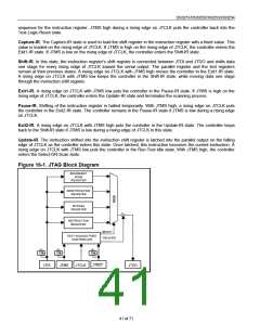
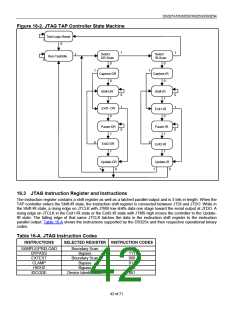
Figure 16-2. JTAG TAP Controller State Machine
Test-Logic-Reset
1
0
1
1
Select
Select
1
Run-Test/Idle
DR-Scan
IR-Scan
0
0
0
1
1
Capture-DR
0
Capture-IR
0
Shift-DR
1
Shift-IR
1
0
1
0
1
Exit1- DR
0
Exit1-IR
0
Pause-DR
1
Pause-IR
1
0
0
0
0
Exit2-DR
1
Exit2-IR
1
Update-DR
Update-IR
1
0
1
0
16.3 JTAG Instruction Register and Instructions
The instruction register contains a shift register as well as a latched parallel output and is 3 bits in length. When the
TAP controller enters the Shift-IR state, the instruction shift register is connected between JTDI and JTDO. While in
the Shift-IR state, a rising edge on JTCLK with JTMS low shifts data one stage toward the serial output at JTDO. A
rising edge on JTCLK in the Exit1-IR state or the Exit2-IR state with JTMS high moves the controller to the Update-
IR state. The falling edge of that same JTCLK latches the data in the instruction shift register to the instruction
parallel output. Table 16-A shows the instructions supported by the DS325x and their respective operational binary
codes.
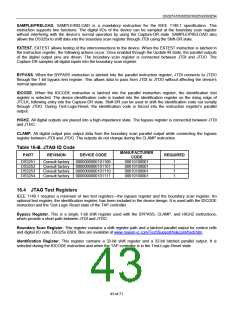
Table 16-A. JTAG Instruction Codes
INSTRUCTIONS
SELECTED REGISTER INSTRUCTION CODES
SAMPLE/PRELOAD
Boundary Scan
010
111
000
011
100
001
BYPASS
Bypass
EXTEST
Boundary Scan
Bypass
CLAMP
HIGHZ
Bypass
IDCODE
Device Identification
42 of 71

 DALLAS [ DALLAS SEMICONDUCTOR ]