DS3251/DS3252/DS3253/DS3254
16. JTAG TEST ACCESS PORT AND BOUNDARY SCAN
16.1 JTAG Description
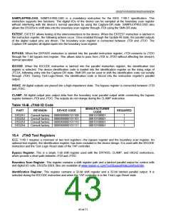
The DS325x LIUs support the standard instruction codes SAMPLE/PRELOAD, BYPASS, and EXTEST. Optional
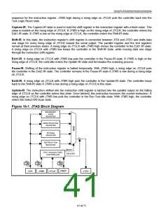
public instructions included are HIGHZ, CLAMP, and IDCODE. Figure 16-1 features a block diagram. The LIUs
contain the following items, which meet the requirements set by the IEEE 1149.1 Standard Test Access Port and
Boundary Scan Architecture:
Test Access Port (TAP)
TAP Controller
Bypass Register
Boundary Scan Register
Device Identification Register
Instruction Register
The TAP has the necessary interface pins, namely JTCLK, JTRST, JTDI, JTDO, and JTMS. Details on these pins
can be found in Table 6-A. Details about the boundary scan architecture and the TAP can be found in IEEE
1149.1-1990, IEEE 1149.1a-1993, and IEEE 1149.1b-1994.
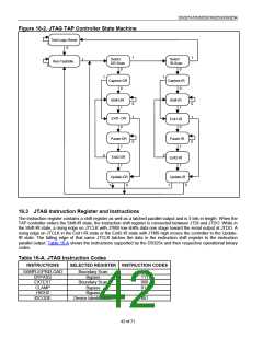
16.2 JTAG TAP Controller State Machine Description
This section discusses the operation of the TAP controller state machine. The TAP controller is a finite state
machine that responds to the logic level at JTMS on the rising edge of JTCLK. Each of the states denoted in Figure
16-2 are described in the following pages.
Test-Logic-Reset. Upon device power-up, the TAP controller starts in the Test-Logic-Reset state. The instruction
register contains the IDCODE instruction. All system logic on the device operates normally.
Run-Test-Idle. Run-Test-Idle is used between scan operations or during specific tests. The instruction and test
registers remain idle.
Select-DR-Scan. All test registers retain their previous state. With JTMS low, a rising edge of JTCLK moves the
controller into the Capture-DR state and initiates a scan sequence. JTMS high moves the controller to the Select-
IR-SCAN state.
Capture-DR. Data can be parallel loaded into the test data registers selected by the current instruction. If the
instruction does not call for a parallel load or the selected register does not allow parallel loads, the test register
remains at its current value. On the rising edge of JTCLK, the controller goes to the Shift-DR state if JTMS is low or
to the Exit1-DR state if JTMS is high.
Shift-DR. The test data register selected by the current instruction is connected between JTDI and JTDO and shifts
data one stage toward its serial output on each rising edge of JTCLK. If a test register selected by the current
instruction is not placed in the serial path, it maintains its previous state.
Exit1-DR. While in this state, a rising edge on JTCLK with JTMS high puts the controller in the Update-DR state,
which terminates the scanning process. A rising edge on JTCLK with JTMS low puts the controller in the Pause-DR
state.
Pause-DR. Shifting of the test registers is halted while in this state. All test registers selected by the current
instruction retain their previous state. The controller remains in this state while JTMS is low. A rising edge on
JTCLK with JTMS high puts the controller in the Exit2-DR state.
Exit2-DR. While in this state, a rising edge on JTCLK with JTMS high puts the controller in the Update-DR state
and terminates the scanning process. A rising edge on JTCLK with JTMS low puts the controller in the Shift-DR
state.
Update-DR. A falling edge on JTCLK while in the Update-DR state latches the data from the shift register path of
the test registers into the data output latches. This prevents changes at the parallel output because of changes in
the shift register. A rising edge on JTCLK with JTMS low puts the controller in the Run-Test-Idle state. With JTMS
high, the controller enters the Select-DR-Scan state.
Select-IR-Scan. All test registers retain their previous state. The instruction register remains unchanged during this
state. With JTMS low, a rising edge on JTCLK moves the controller into the Capture-IR state and initiates a scan
40 of 71

 DALLAS [ DALLAS SEMICONDUCTOR ]