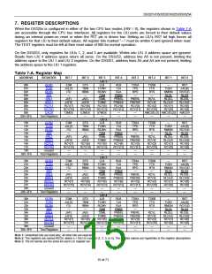
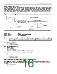
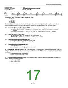
DS3251/DS3252/DS3253/DS3254
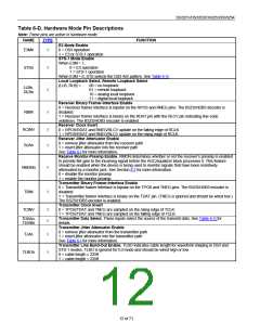
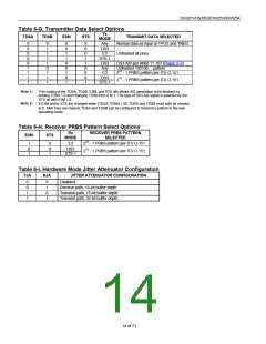
Table 6-G. Transmitter Data Select Options
Tx
TDSA
TDSB
E3M
STS
TRANSMIT DATA SELECTED
MODE
Any
0
0
0
0
0
1
1
1
1
0
1
1
1
1
0
1
1
1
X
0
1
1
0
X
1
0
1
X
0
0
1
1
X
0
X
1
Normal data as input at TPOS and TNEG
DS3
E3
Unframed all ones
STS-1
DS3
Any
DS3 AIS per ANSI T1.107 (Figure 9-2)
Unframed 100100… pattern
E3
223 - 1 PRBS pattern per ITU O.151
DS3
STS-1
215 - 1 PRBS pattern per ITU O.151
Note 1:
This coding of the TDSA, TDSB, E3M, and STS bits allows AIS generation to be enabled by
holding TDSA = 0 and changing TDSB from 0 to 1. The type of DS3 AIS signal is selected by the
STS bit with E3M = 0.
Note 2:
If E3M and/or STS are changed when {TDSA,TDSB} U 00, TDSA and TDSB must both be cleared
to 0. After they are cleared, TDSA and TDSB can be configured to transmit a pattern in the new
operating mode.
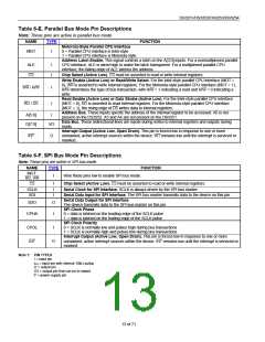
Table 6-H. Receiver PRBS Pattern Select Options
Rx
RECEIVER PRBS PATTERN
SELECTED
E3M
STS
MODE
1
0
E3
223 - 1 PRBS pattern per ITU O.151
215 - 1 PRBS pattern per ITU O.151
0
X
DS3
1
1
STS-1
Table 6-I. Hardware Mode Jitter Attenuator Configuration
TJA
RJA
JITTER ATTENUATOR CONFIGURATION
Disabled
Receive path, 16-bit buffer depth
Transmit path, 16-bit buffer depth
Transmit path, 32-bit buffer depth
0
0
1
1
0
1
0
1
14 of 71

 DALLAS [ DALLAS SEMICONDUCTOR ]