DS3251/DS3252/DS3253/DS3254
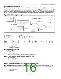
Status Register Description
The status registers have two types of status bits. Real-time status bits—located in the SR registers—indicate the
state of a signal at the time it was read. Latched status bits—located in the SRL registers—are set when a signal
changes state (low-to-high, high-to-low, or both, depending on the bit) and cleared when written with a logic 1
value. After clearing, latched status bits remain cleared until the signal changes state again. Interrupt-enable bits—
located in the SRIE registers—control whether or not the INT pin is driven low when latched register bits are set.
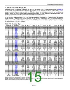
Figure 7-1. Status Register Logic
REAL-TIME STATUS
EVENT
SR
LATCHED STATUS
LATCHED STATUS REGISTER
SET ON EVENT DETECT
SRL
CLEAR ON WRITE LOGIC 1
WR
INT
INT ENABLE
REGISTER
WR
OTHER INT
SOURCE
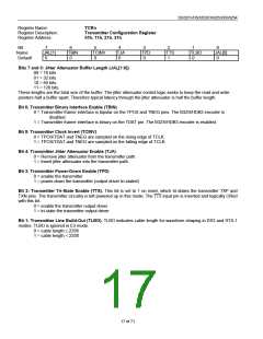
Register Name:
GCRn
Register Description:
Register Address:
Global Configuration Register
00h, 10h, 20h, 30h
Bit
7
E3M
0
6
STS
0
5
LLB
0
4
RLB
0
3
TDSA
0
2
TDSB
0
1
0
Name
Default
—
—
RST
0
Bit 7: E3 Mode Enable (E3M)
0 = DS3 operation
1 = E3 or STS-1 operation
Bit 6: STS-1 Mode Enable (STS)
When E3M = 1,
0 = E3 operation
1 = STS-1 operation
When E3M = 0, STS selects the DS3 AIS pattern (Table 6-G).
Bits 5, 4: Local Loopback, Remote Loopback Select (LLB, RLB)
00 = no loopback
01 = remote loopback
10 = analog local loopback
11 = digital local loopback
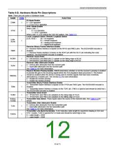
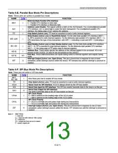
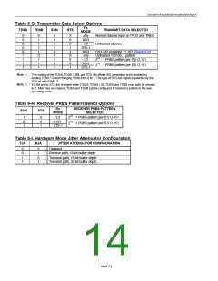
Bits 3, 2: Transmitter Data Select (TDSA, TDSB). See Table 6-G for details.
Bit 0: Reset (RST). When this bit is high, the digital logic of the LIU is held in reset and all registers for that LIU
(except the RST bit) are forced to their default values. RST is cleared to 0 at power-up and when the RST pin is
activated.
0 = normal operation
1 = reset LIU
16 of 71

 DALLAS [ DALLAS SEMICONDUCTOR ]