60
8Bit Single Chip Microcontroller
DMC73C168
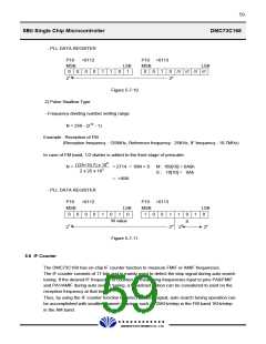
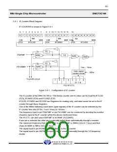
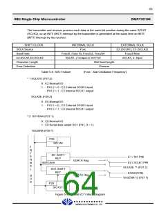
5.8.1. IF Counter Block Diagram
IF COUNTER is shown in Figure 5.8.1.
0
4
8
9 10 11 12 13 14 15
16
1
1
2
2
3
3
5
5
6
6
7
7
0
4
0
1
2
3
4
5
6
7
0 X X X X X X X
1bit
8bit
IFCLSD
8bit
LSB
MSB
LSB
P24
MSB LSB
P25
MSB
P23
IFCMSD
IFCHSD
TG
PA0/FMIF
NAN
NAN
1/2
NAN
AND
TG
PA1/AMIF
1ms ~ 15ms
Gate signal
control circuit
1KHz
To portA circuit
3
2
1
0
7
6
5
P22 IFCCTL
Figure 5-8-1. Configuration of IF counter
4
I F T B
The IF counter of the DMC73C168 is 17bit binary counter and its value can be read the IFCLSD
(P23), IFCMSD (P24) and IFCHSD (P25).
IFCLSD, IFCMSD and IFCHSD are Registers for reading only, and data cannot be set in the IF
counter through these Registers.
One of the fifteen following count times (gate signals) of the IF counter can be selected by the
IF counter time bits (IFTB) : From 1msec to 15msec.
The frequency input to pin PA0/FMIF or pin PA1/AMIF can be countered by deciding the number
of pulses input to the IF counter within the above-mentioned times.
The IFCCTL can also select A0/FMIF or A1/AMIF (P22;bit6/5).
If one pin is selected the other pin is internally pulled down automatically through a resister.
The maximum frequency that can be input to pin A0/FMIF is 20MHz (Vin=0.1 Vp.p) and that
of pin A1/AMIF is 5MHz (Vin=0.1 Vp.p)
The signal input to pin A1/AMIF is input directly to the IF counter.
The signal input to pin A0/FMIF is input to the IF counter internally through the 1/2 frequency
divider.
£Ä£Á£Å£×£Ï £Ï
DAEWOO ELECTRONICS CO., LTD.

 DAEWOO [ DAEWOO Electronic Components ]