61
8Bit Single Chip Microcontroller
DMC73C168
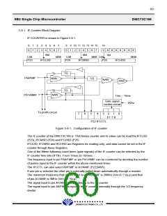
Therefore, the value of the IF counter will be 1/2 to the actual frequency to be input to pin A0/
FMIF if pin A1/AMIF is selected. The IF counter is reset during power ON reset (VDD = low to
high) and IF counter holds the present values when the counter is stopped. This values can be
cleared by program (IFCCTL;bit7). When the IF counter enters a halt mode, it maintains the state
before the halt state.
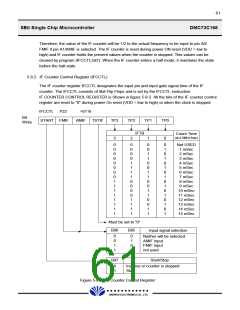
5.8.2. IF Counter Control Register (IFCCTL)
The IF counter register IFCCTL designates the input pin and input gate signal time of the IF
counter. The IFCCTL consists of 8bit Flip Flops and is set by the IFCCTL instruction.
IF COUNTER CONTROL REGISTER is Shown in figure 5-8-2. All the bits of the IF counter control
register are reset to "0" during power On reset (VDD = low to high) or when the clock is stopped.
IFCCTL P22
START FMIF
>0116
AMIF
Bit
Write
TSTIF
TP3
3
TP2
2
TP1
1
TP0
0
IFTB
Count Time
(at 4.5MHz fosc)
0
0
0
0
0
0
0
0
1
1
1
1
1
1
1
1
0
0
0
0
1
1
1
1
0
0
0
0
1
1
1
1
0
0
1
1
0
0
1
1
0
0
1
1
0
0
1
1
0
1
0
1
0
1
0
1
0
1
0
1
0
1
0
1
Not USED
1 mSec
2 mSec
3 mSec
4 mSec
5 mSec
6 mSec
7 mSec
8 mSec
9 mSec
10 mSec
11 mSec
12 mSec
13 mSec
14 mSec
15 mSec
Must be set to "0"
Bit6
Bit5
Input signal selection
0
0
1
1
0
1
0
1
Neither will be selected
AMIF input
FMIF input
not used
Bit7
Start/Stop
0
1
Inactive or counter is stopped
Start
Figure 5-8-2. IF Counter Control Register
£Ä£Á£Å£×£Ï £Ï
DAEWOO ELECTRONICS CO., LTD.

 DAEWOO [ DAEWOO Electronic Components ]