58
8Bit Single Chip Microcontroller
DMC73C168
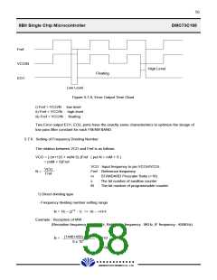
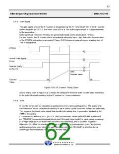
Fref
VCO/N
High Level
Floating
EO1
Low Level
Figure 5-7-9, Error Output Time Chart
i) Fref > VCO/N : low level
ii) Fref < VCO/N : high level
iii) Fref = VCO/N : floating
Two Error output EO1, EO2, ports have the exactly same characteristics to optimize the design of
low pass filter constant for each FM/AM BAND.
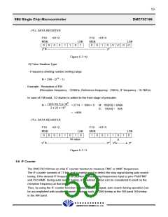
5.7.6. Setting of Frequency Dividing Number
The relation between VCO and Fref is as follows.
VCO = { (m+1)S + m(M-S) }Fref ( put N = mM + S )
= (mM + S)Fref
VCO : Input frequency to pin VCOH/VCOL
VCO
N =
Fref : Reference frequency
Fref
m
s
: STANDARD Prescaler Ratio (=16)
: The bit number of swallow counter
: The bit number of programmable counter
M
1) Direct dividing type
- Frequency dividing number setting range
N = 16 ~ (212 - 1) => 10 ~ >FFF
Example : Reception of MW
(Reception frequency : 1440KHz, Reference frequency : 9KHz, IF frequency : 450KHz)
(1440+450) x 103
N =
= 210
9 x 103
= >0D2
£Ä£Á£Å£×£Ï £Ï
DAEWOO ELECTRONICS CO., LTD.

 DAEWOO [ DAEWOO Electronic Components ]