62
8Bit Single Chip Microcontroller
DMC73C168
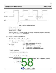
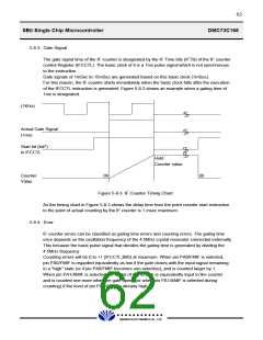
5.8.3. Gate Signal
The gate signal time of the IF counter is designated by the IF Time bits (IFTB) of the IF counter
control Register (IFCCTL). The basic clock of it is a 1ms pulse signal which is not synchronous
to the instruction.
Gate signals of 1mSec to 15mSec are generated based on this basic clock (1mSec).
For this reason, the IF counter starts immediately when the basic clock falls after the execution
of the IFCCTL instruction is generated. Figure 5-8-3 shows an example when a gating time of
1ms is designated.
(1KHz)
Actual Gate Signal
(1ms)
Start bit (bit7)
in IFCCTL
Hold
Counter value
Counter
Value
00
00
Figure 5-8-3. IF Counter Timing Chart.
As the timing chart in Figure 5-8-3 shows the delay time from the point counter start instruction
to the point of actual counting by the IF counter is 1 msec maximum.
5.8.4. Error
IF counter errors can be classified as gating time errors and counting errors. The gating time
error depends on the oscillation frequency of the 4.5MHz crystal resonator connected externally.
This because the basic pulse signal that decides the gating time is generated by dividing the
4.5MHz frequency.
Counting errors will be 0 to +1 (IFCCTL;Bit0) at maximum. When pin PA0/FMIF is selected,
pin PA0/FMIF is regarded equivalently as low if the gate closes with the input signal remaining
in a "high" state (or if pin PA0/FMIF becomes non-selective), and is counted larger by 1.
When pin PA1/AMIF is selected the signal of low to high is equivalently input to the counter
and is counted one more when the gate opens (or when pin PA1/AMIF is selected during
counting) if the level of pin PA1/AMIF is already high.
£Ä£Á£Å£×£Ï £Ï
DAEWOO ELECTRONICS CO., LTD.

 DAEWOO [ DAEWOO Electronic Components ]