56
8Bit Single Chip Microcontroller
DMC73C168
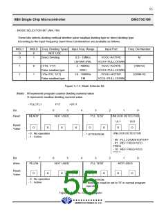
¤· READY
This bit must be set to satisfy The PLL conditions between PLL ON/START STATUS and PLL
OFF/STOP STATUS by programming.
¤· PLLEN BIT
When the PLL ON/START (PLLEN=1) OR PLL OFF/STOP (PLLEN=0) is set to PLLCTL1
register (P17), the READY bit will be set to 1 or 0 accordingly.
¤· UNLOCK DETECTOR BIT
This bit is automatically set by phase detector conditions.
Both the UL1 bit and UL0 bit are automatically set under conditions of PLL LOCK/STOP/OFF.
When reference frequency leads VCO frequency which is divided by programmable divider
(Fref>VCO/N), the UL1 bit is set to 0 and the UL0 bit is set to 1. When reference frequency
lags VCO frequency which is divided by programmable divider (Fref>VCO/N), the UL1 bit is
set to 1 and the UL0 bit is set to 0.
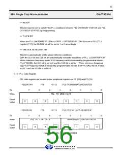
5.7.3 PLL Data Register
PLL data register are located in two peripheral registers as PF (18) and PF (19).
- PLLDATAH
7
P18
>0112
: PLL PC MSB DATA REGISTER
Bit
6
5
4
3
2
1
0
Write
PLL PC MSB DATA
Reset
Value
O
X
X
X
O
O
O
O
- PLLDATAL
7
P19
>0113
: PLL PC LSB DATA REGISTER
Bit
6
5
4
3
2
1
0
Write
PLL PC LSB DATA
SWALLOW COUNTER VALUE
Reset
Value
O
X
X
X
O
O
O
O
Figure 5-7-6. PLL DATA REGISTER
£Ä£Á£Å£×£Ï £Ï
DAEWOO ELECTRONICS CO., LTD.

 DAEWOO [ DAEWOO Electronic Components ]