CY7C9689
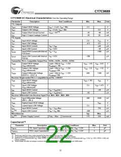
CY7C9689 DC Electrical Characteristics Over the Operating Range
Parameter
Description
Test Conditions
Min.
Max.
Unit
TTL Outputs
V
Output HIGH Voltage
I
I
= −2 mA, V = Min.
2.4
V
V
OHT
OH
OL
DD
V
Output LOW Voltage
= 8 mA, V = Min.
0.4
−80
20
OLT
DD
[13]
I
I
Output Short Circuit Current
High-Z Output Leakage Current
V
= 0V
–30
–20
mA
mA
OST
OZL
OUT
TTL Inputs
V
V
Input HIGH Voltage
Input LOW Voltage
Input HIGH Current
Input LOW Current
2.0
V
V
IHT
ILT
CC
–0.5
0.8
±40
−40
V
I
I
I
V
V
V
= V
DD
µA
µA
µA
IHT
IN
= 0.0V
ILT
IN
IN
Input HIGH Current with Internal
Pull-Down
= V
+300
ILPDT
CC
I
Input LOW Current with Internal
Pull-Up
V
= 0.0V
–300
µA
ILPUT
IN
Transmitter PECL-Compatible Output Pins: OUTA+, OUTA , OUTB+, OUTB
−
−
V
Output HIGH Voltage
Load = 50Ω to V − 1.33V
V
− 1.03
V
V
− 0.83
V
V
OHE
DD
DD
DD
DD
(V referenced)
R
= 10k
DD
CURSET
V
Output LOW Voltage
Load = 50Ω to V − 1.33V
V − 2.0
DD
− 1.62
OLE
DD
(V referenced)
R
=10k
DD
CURSET
V
Output Differential Voltage
Load = 50Ω to V − 1.33V
600
1100
mV
ODIF
DD
|(OUT+) − (OUT−)|
R
=10k
CURSET
Receiver Single-ended PECL-Compatible Input Pin: CARDET
V
Input HIGH Voltage
V
−1.165
V
DD
V
V
IHE
DD
(V referenced)
DD
V
Input LOW Voltage
2.5
V
−1.475
DD
ILE
(V referenced)
DD
I
I
Input HIGH Current
Input LOW Current
V
V
= V (min.)
+40
µA
µA
IHE
IN
IN
IHE
= V (max.)
–40
ILE
ILE
Receiver Differential Line Receiver Input Pins: INA+, INA , INB+, INB
−
−
V
Input Differential Voltage
200
2500
mV
DIFF
|(IN+) − (IN−)|
V
V
Highest Input HIGH Voltage
Lowest Input LOW Voltage
Input HIGH Current
V
V
V
IHH
ILL
DD
2.5
I
I
V
V
= V Max.
IHH
750
µA
µA
IHH
[14]
IN
IN
Input LOW Current
= V Min.
−200
Typ.
170
ILL
ILL
Miscellaneous
Max.
[15]
I
Power Supply Current
Freq. = Max.
Commercial
250
mA
DD
Capacitance[16]
Parameter
Description
TTL Input Capacitance
PECL input Capacitance
Test Conditions
T = 25°C, f = 1 MHz, V = 5.0V
Max.
Unit
C
C
7
4
pF
pF
INTTL
A
0
DD
T = 25°C, f = 1 MHz, V = 5.0V
INPECL
A
0
DD
Notes:
13. Tested one output at a time, output shorted for less than one second, less than 10% duty cycle.
14. To guarantee positive currents for all PECL voltages, an external pull-down resistor must be present.
15. Maximum ICC is measured with VDD = MAX, RFEN = LOW, and outputs unloaded. Typical IDD is measured with VDD = 5.0V, TA = 25°C, RFEN = LOW, and
outputs unloaded.
16. Tested initially and after any design or process changes that may affect these parameters, but not 100% tested.
22

 CYPRESS [ CYPRESS ]