CY7C9689
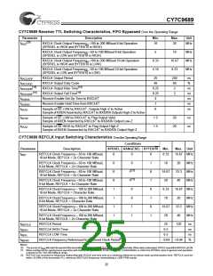
CY7C9689 Receiver Switching Characteristics Over the Operating Range
Parameter
Description
Min.
Max.
5.0
Unit
ns
[23]
t
t
t
t
Bit Time
20.0
B
[16, 24]
Static Alignment
600
ps
SA
[16, 25, 26]
Error Free Window
IN± Peak-to-Peak Input Jitter Tolerance
0.65
UI
EFW
IN_J
[16, 25, 27, 30]
0.5
UI
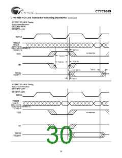
CY7C9689 Transmitter Switching Characteristics Over the Operating Range
Parameter
Description
Min.
20.0
200
200
Max.
5.0
Unit
ns
ps
ps
UI
[23]
t
t
t
t
t
t
Bit Time
PECL Output Rise Time 20−80% (PECL Test Load)
B
[16]
[16]
1700
1700
0.02
0.008
0.08
RISE
FALL
DJ
PECL Output Fall Time 80−20% (PECL Test Load)
[16, 28]
Deterministic Jitter (peak-peak)
[16, 29]
Random Jitter (σ)
UI
RJ
[16]
Transmitter Total Output Jitter (peak-peak)
UI
JT
Notes:
23. The PECL switching threshold is the midpoint between the PECL− VOH, and VOL specification (approximately VDD − 1.33V).
24. Static alignment is a measure of the alignment of the Receiver sampling point to the center of a bit. Static alignment is measured by the absolute difference
of the left and right edge shifts (|tSH_L – tSH_R|) of one bit until a character error occurs.
25. Receiver UI (Unit Interval) is calculated as 1/(fREF*N) when operated in 8-bit mode (N=10) and 10-bit mode (N=12) if no data is being received, or 1/(fREF*N)
of the remote transmitter if data is being received. In an operating link this is equivalent to N * tB when REFCLK = 1X the character rate. An alternate multiply
ratios (2X or 4X, as selected by SPDSEL and RANGESEL), the numerator is multiplied by 2 or 4 respectively.
26. Error Free Window is a measure of the time window between bit centers where a transition may occur without causing a bit sampling error. EFW is measured
over the operating range, input jitter < 50% Dj.
27. The specification is sum of 25% Duty Cycle Distortion (DCD), 10% Data Dependant Jitter (DDJ), 15% Random Jitter (RJ).
28. While sending continuous JK, outputs loaded to 50Ω to VDD−1.3V, over the operating range.
29. While sending continuous HH, after 100,000 samples measured at the cross point of differential outputs, time referenced to REFCLK input, over the operating
range
30. Parallel data output specifications are only valid if all outputs are loaded with similar DC and AC loads.
26

 CYPRESS [ CYPRESS ]