CY7C9689
Clock Divider
character sequence that includes all Data and Command
Character codes, including the explicit violation symbols. This
provides a predictable but pseudo-random sequence that can
be matched to an identical LFSR in the Transmitter. When syn-
chronized with the received data stream, it checks each char-
acter in the Decoder with each character generated by the
LFSR and indicates compare errors at the VLTN output of the
Receive Output Register.
This block contains the clock division logic, used to transfer the
data from the Deserializer/Framer to the Decoder once every
character (once every ten or twelve bits) clock. This counter is
free running and generates outputs at the bit-rate divided by
10 (12 when the BYTE8/10 is LOW). When the Receive FIFO
is bypassed, one of these generated clocks is driven out the
RXCLK pin.
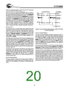
The LFSR is initialized by the BIST hardware to the BIST loop
start code of HEX data 00 (00 is sent only once per BIST loop).
Once the start of the BIST loop has been detected by the re-
ceiver, RXRVS is asserted for pattern mismatches between
the received characters and the internally generated character
sequence. Code rule violations or running disparity errors that
occur as part of the BIST loop do not cause an error indication.
RXFULL pulses asserted for one RXCLK cycle per BIST loop and
can be used to check test pattern progress.
Deserializer/Framer
The CDR circuit extracts bits from the serial data stream and
clocks these bits into the Shifter/Framer at the bit-clock rate.
When enabled, the Framer examines the data stream looking
for JK or LM (when BYTE8/10 is LOW) characters at all possi-
ble bit positions. The location of this character in the data
stream is used to determine the character boundaries of all
following characters.
The specific patterns checked by the receiver are described in
Table 4.
The framer operates in two different modes, as selected by the
RFEN input. When RFEN is asserted (HIGH), the framer is
allowed to reset the internal character boundaries on any de-
tected JK or LM (when BYTE8/10 is LOW) character.
If a large number of errors are detected, the receive BIST state
machine aborts the compare operations and resets the LFSR
to the D0.0 state to look for the start of the BIST sequence
again.
If RFEN is LOW, the framer is disabled and no changes are
made to character boundaries.
The framer in the CY7C9689 operates by shifting the internal
character position to align with the character clock. This en-
sures that the recovered clock does not contain any significant
phase changes/hops during normal operation or framing, and
allows the recovered clock to be replicated and distributed to
other circuits using PLL-based logic elements.
Receive Control State Machine
The Receive Control State Machine responds to multiple input
conditions to control the routing and handling of received char-
acters. It controls the staging of characters across various reg-
isters and the Receive FIFO. It controls the various discard
policies and error control within the receiver, and operates in
response to:
Decoder Block
•the received character stream
The decoder logic block performs two primary functions: de-
coding the received transmission characters back into Data
and Command Character codes, and comparing generated
BIST patterns with received characters to permit at-speed link
and device testing.
•the room for additional data in the Receive FIFO
•the state of the receiver BIST enable (RXBISTEN)
•the state of FIFOBYP
These signals and conditions are used by the Receive Control
State Machine to control the Receive Formatter, write access
to the Receive FIFO, the Receive Output register, and BIST.
They determine the content of the characters passed to each
of these destinations,
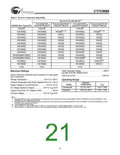
5B/4B, 6B/5B Decoder
The framed parallel output of the Deserializer is passed to the
5B/4B, 6B/5B Decoder. If the Decoder is enabled, it is trans-
formed from a 10-bit or 12-bit transmission character back to
the original Data and Command Character codes. This block
uses the standard decoder patterns in Table 7 and Table 8 of
this data sheet. Data Patterns on the data bus are indicated by
a LOW on RXSC/D, and Command Character codes on the com-
mand bus are indicated by a HIGH. Invalid patterns or disparity er-
rors are signaled as errors by a HIGH on VLTN.
The Receive Control State Machine always operates synchro-
nous to the recovered character clock (bit-clock/10 or bit-
clock/12). When the Receive FIFO is bypassed, RXCLK be-
comes an output that changes synchronous to the internal
character clock. RXCLK operates at the same frequency as
the internal character clock.
If the Decoder is bypassed and BYTE8/10 is HIGH, the ten
(10) data bits of each transmission character are passed un-
changed from the framer to the Pipeline Register.
Discard Policies
When the Receive FIFO is enabled, the Receive Control State
Machine has the ability to selectively discard specific charac-
ters from the data stream that are determined by the present
configuration as being unnecessary. When discarding is en-
abled, it reduces the host system overhead necessary to keep
the Receive FIFO from overflowing and losing data.
When the Decoder is bypassed and BYTE8/10 is LOW, the
twelve (12) data bits of each transmission character are
passed unchanged from the framer to the Pipeline Register.
BIST LFSR
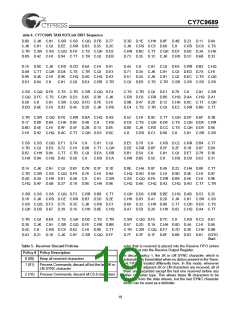
The discard policy is configured as part of the operating mode
and is set using the RXMODE[1:0] inputs. The four discard
policies are listed in Table 5.
The output register of the Decoder block is normally used to
accumulate received characters for delivery to the Receive
Formatter block. When configured for BIST mode (RXBISTEN
is LOW), this register becomes a signature pattern generator
and checker by logically converting to a Linear Feedback Shift
Register (LFSR). When enabled, this LFSR generates a 511-
Policy 0 is the simplest and also applies for all conditions
where the Receive FIFO is bypassed. In this mode, every char-
18

 CYPRESS [ CYPRESS ]