CY7C9689
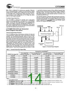
Table 3. Speed Select and Range Select Settings
tion greater than 9 dB (V
> 200 mV, or 400 mV peak-to-peak
DIF
differential) or can be directly connected to +5V fiber-optic interface
modules (any ECL logic family, not limited to ECL 100K). The com-
mon-mode tolerance of these line receivers accommodates a wide
range of signal termination voltages.
[7]
Serial
REFCLK
Data Rate
(MBaud)
Frequency
(MHz)
SPDSEL
LOW
RANGESEL
LOW
50–100
50–100
10–20
20–40
10–20
20–40
As can be seen in Table 2, these inputs are configured to allow
single-pin control for most applications. For those systems requiring
selection of only INA± or INB±, the DLB signals can be tied LOW,
and the A/B selection can be performed using only A/B. For those
systems requiring only a single input and a local loopback, the A/B
can be tied HIGH or LOW, and DLB can be used for loopback con-
trol.
[6]
LOW
HIGH
HIGH
LOW
100–200
100–200
HIGH
HIGH
Notes:
6.When SPDSEL is LOW and the FIFOs are bypassed (FIFOBYP is LOW),
the RANGESEL input is ignored and is internally mapped to the LOW
setting.
7.When configured for 12-bit pre-encoded data (BYTE8/10 and ENCBYPare
both LOW) the allowable REFCLK ranges are 8.33 to 16.67 MHz and
16.67 to 33.33 MHz.
Signal Detect
The selected Line Receiver (that routed to the clock and data
recovery PLL) is simultaneously monitored for:
•analog amplitude (>400 mV pk-pk)
•transition density
•received data stream outside normal frequency range
(±400 ppm)
•the state of the transmitter BIST enable (TXBISTEN)
•the state of external halt signal (TXHALT)
These signals are used by the Transmit Control State Machine
to control the data formatter, read access to the Transmit FIFO
and BIST. They determine the content of the characters
passed to the Encoder and Transmit Shifter.
•and carrier detected.
All of these conditions must be valid for the Signal Detect block
to indicate a valid signal is present. This status is presented on
the LFI (Link Fault Indicator) output, which changes synchro-
nous to RXCLK. While link status is monitored internally at all
times, it is necessary to have transitions on RXCLK to allow
this signal to change externally.
When the Transmit FIFO is bypassed, the Transmit Control
State Machine operates synchronous to REFCLK. In this
mode, data from the TXDATA bus is passed directly from the
Input Register to the Pipeline Register. If no data is enabled
into the Input register (TXEN is deasserted or TXFULL is as-
serted) then the Transmit Control State Machine presents a JK
or LM (when BYTE8/10 = LOW) Command Character code to
the Encoder to maintain link synchronization.
Clock/Data Recovery
The extraction of a bit-rate clock and recovery of data bits from
the received serial stream is performed within the Clock/Data
Recovery (CDR) block. The clock extraction function is per-
formed by a high-performance embedded phase-locked loop
(PLL) that tracks the frequency of the incoming bit stream and
aligns the phase of its internal bit-rate clock to the transitions
in the serial data stream.
If both the Encoder and Transmit FIFO are bypassed and no
data is enabled into the Input Register, the Transmit Control
State Machine injects JK or LM (when BYTE8/10 = LOW) into
the Serial Shifter Register at this time slot. This also occurs if
the Encoder is bypassed, the Transmit FIFO is enabled, and
the Transmit FIFO is empty.
The CDR makes use of the clock present at the REFCLK input.
It is used to ensure that the VCO (within the CDR) is operating
at the correct frequency (rather than some harmonic of the bit
rate), to improve PLL acquisition time, and to limit unlocked
frequency excursions of the CDR VCO when no data is
present at the serial inputs.
External Control of Data Flow
The Transmit Control State Machine supports halting of data
transmission by the TXHALT input. This control signal input is
only interpreted when the Transmit FIFO is enabled. TXHALT
is brought directly to the state machine without going through
the Transmit FIFO.
Regardless of the type of signal present, the CDR will attempt
to recover a data stream from it. If the frequency of the recov-
ered data stream is outside the limits for the range controls,
the CDR PLL will track REFCLK instead of the data stream.
When the frequency of the selected data stream returns to a
valid frequency, the CDR PLL is allowed to track the received
data stream. The frequency of REFCLK is required to be within
±400 ppm of the frequency of the clock that drives the REF-
CLK signal at the remote transmitter to ensure a lock to the
incoming data stream.
The assertion of TXHALT causes character processing to stop
at the next FIFO character location. No additional data is read
from the Transmit FIFO until TXHALT is deasserted
TXHALT may be used to prevent a remote FIFO overflow,
which would result in lost data. This back-pressure mechanism
can significantly improve data integrity in systems that cannot
guarantee the full bandwidth of the host system at all times
Serial Line Receivers
For systems using multiple or redundant connections, the LFI
output can be used to select an alternate data stream. When
an LFI indication is detected, external logic can toggle selec-
tion of the INA± and INB± inputs through the A/B input. When
a port switch takes place, it is necessary for the PLL to re-
acquire the new serial stream and frame to the incoming char-
acters.
Two differential line receivers, INA± and INB±, are available for
accepting serial data streams, with the active input selected
using the A/B input. The DLB input allow the transmit Serializer
output to be selected as a third input serial stream, but this path
isgenerally used only for local diagnostic loopback purposes. The
serial line receiver inputs are all differential, and will accommodate
wire interconnect with filtering losses or transmission line attenua-
17

 CYPRESS [ CYPRESS ]