CY7C68013A, CY7C68014A
CY7C68015A, CY7C68016A
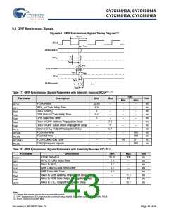
9.6 GPIF Synchronous Signals
Figure 9-6. GPIF Synchronous Signals Timing Diagram[20]
t
IFCLK
IFCLK
t
SGA
GPIFADR[8:0]
RDY
X
t
SRY
t
RYH
DATA(input)
valid
t
SGD
t
DAH
CTLX
t
XCTL
DATA(output)
N
N+1
t
XGD
Table 17. GPIF Synchronous Signals Parameters with Internally Sourced IFCLK[20, 21]
Typ
Parameter
tIFCLK
Description
Min
Max
Unit
Min
–
Max
–
IFCLK Period
20.83
–
–
ns
ns
ns
ns
ns
ns
ns
ns
ps
ps
%
tSRY
RDYX to Clock Setup Time
Clock to RDYX
8.9
0
–
–
tRYH
–
–
–
tSGD
GPIF Data to Clock Setup Time
GPIF Data Hold Time
9.2
0
–
–
–
tDAH
–
–
–
tSGA
Clock to GPIF Address Propagation Delay
Clock to GPIF Data Output Propagation Delay
Clock to CTLX Output Propagation Delay
IFCLK rise time
–
7.5
11
6.7
–
–
–
tXGD
–
–
–
tXCTL
tIFCLKR
tIFCLKF
tIFCLKOD
tIFCLKJ
–
–
–
–
–
900
900
51
300
IFCLK fall time
–
–
–
IFCLK Output duty cycle
–
–
49
–
IFCLK jitter peak to peak
–
–
ps
Table 18. GPIF Synchronous Signals Parameters with Externally Sourced IFCLK[21]
Parameter Description
Min
20.83
2.9
3.7
3.2
4.5
–
Max
200
–
Unit
tIFCLK
tSRY
tRYH
tSGD
tDAH
tSGA
tXGD
tXCTL
IFCLK Period[22]
ns
ns
ns
ns
ns
ns
ns
ns
RDYX to Clock Setup Time
Clock to RDYX
–
GPIF Data to Clock Setup Time
GPIF Data Hold Time
–
–
Clock to GPIF Address Propagation Delay
Clock to GPIF Data Output Propagation Delay
Clock to CTLX Output Propagation Delay
11.5
15
10.7
–
–
Notes
20. Dashed lines denote signals with programmable polarity.
21. GPIF asynchronous RDY signals have a minimum setup time of 50 ns when using internal 48 MHz IFCLK.
x
22. IFCLK must not exceed 48 MHz.
Document #: 38-08032 Rev. *V
Page 43 of 66

 CYPRESS [ CYPRESS ]