CY7C64013
CY7C64113
7
6
5
4
3
2
1
0
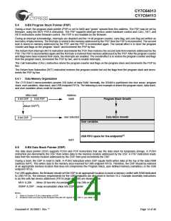
P0[7]
P0[6]
P0[5]
P0[4]
P0[3]
P0[2]
P0[1]
P0[0]
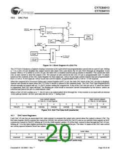
Figure 9-2. Port 0 Data 0x00 (read/write)
7
6
5
4
3
2
1
0
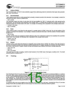
P1[7]
P1[6]
P1[5]
P1[4]
P1[3]
P1[2]
P1[1]
P1[0]
Figure 9-3. Port 1 Data 0x01 (read/write)
7
6
5
4
3
2
1
0
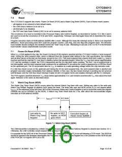
P2[7]
P2[6]
P2[5]
P2[4]
P2[3]
P2[2]
P2[1]
P2[0]
Figure 9-4. Port 2 Data 0x02 (read/write)
7
6
5
4
3
2
1
0
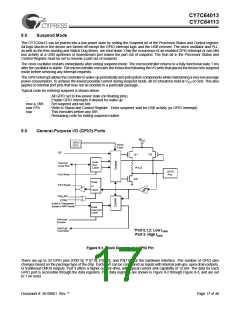
P3[7]
P3[6]
P3[5]
P3[4]
P3[3]
P3[2]
P3[1]
P3[0]
(see text)
Figure 9-5. Port 3 Data 0x03 (read/write)
Special care should be taken with any unused GPIO data bits. An unused GPIO data bit, either a pin on the chip or a port bit that
is not bonded on a particular package, must not be left floating when the device enters the suspend state. If a GPIO data bit is
left floating, the leakage current caused by the floating bit may violate the suspend current limitation specified by the USB
Specifications. If a ‘1’ is written to the unused data bit and the port is configured with open drain outputs, the unused data bit
remains in an indeterminate state. Therefore, if an unused port bit is programmed in open-drain mode, it must be written with a
‘0.’ Notice that the CY7C64013 part always requires that the data bits P1[7:3], P2[7,1,0], and P3[7:3] be written with a ‘0.’
In normal non-HAPI mode, reads from a GPIO port always return the present state of the voltage at the pin, independent of the
settings in the Port Data Registers. If HAPI mode is activated for a port, reads of that port return latched data as controlled by
the HAPI signals (see Section 14.0). During reset, all of the GPIO pins are set to a high-impedance input state (‘1’ in open drain
mode). Writing a ‘0’ to a GPIO pin drives the pin LOW. In this state, a ‘0’ is always read on that GPIO pin unless an external
source overdrives the internal pull-down device.
9.1
GPIO Configuration Port
Every GPIO port can be programmed as inputs with internal pull-ups, open drain outputs, and traditional CMOS outputs. In
addition, the interrupt polarity for each port can be programmed. With positive interrupt polarity, a rising edge (‘0’ to ‘1’) on an
input pin causes an interrupt. With negative polarity, a falling edge (‘1’ to ‘0’) on an input pin causes an interrupt. As shown in the
table below, when a GPIO port is configured with CMOS outputs, interrupts from that port are disabled. The GPIO Configuration
Port register provides two bits per port to program these features. The possible port configurations are detailed in Table 9-1:
Table 9-1. Port Configurations
Port Configuration bits
Pin Interrupt Bit
Driver Mode
Resistive
Interrupt Polarity
11
0
1
0
1
0
1
0
1
Disabled
Resistive
–
10
01
CMOS Output
Open Drain
Open Drain
Open Drain
Open Drain
Open Drain
Disabled
Disabled
Disabled
–
00
Disabled (Default Condition)
+
(Reset State)
In “Resistive” mode, a 14-kΩ pull-up resistor is conditionally enabled for all pins of a GPIO port. An I/O pin is driven HIGH through
a 14-kΩ pull-up resistor when a ‘1’ has been written to the pin. The output pin is driven LOW with the pull-up disabled when a ‘0’
has been written to the pin. An I/O pin that has been written as a ‘1’ can be used as an input pin with the integrated 14-kΩ pull-up
resistor. Resistive mode selects a negative (falling edge) interrupt polarity on all pins that have the GPIO interrupt enabled.
Document #: 38-08001 Rev. **
Page 18 of 48

 CYPRESS [ CYPRESS ]