CY7C64013
CY7C64113
5.6
Address Modes
The CY7C64013 and CY7C64113 microcontrollers support three addressing modes for instructions that require data operands:
data, direct, and indexed.
5.6.1
Data (Immediate)
“Data” address mode refers to a data operand that is actually a constant encoded in the instruction. As an example, consider the
instruction that loads A with the constant 0xD8:
• MOV A,0D8h
This instruction requires two bytes of code where the first byte identifies the “MOV A” instruction with a data operand as the
second byte. The second byte of the instruction is the constant “0xD8.” A constant may be referred to by name if a prior “EQU”
statement assigns the constant value to the name. For example, the following code is equivalent to the example shown above:
• DSPINIT: EQU 0D8h
• MOV A,DSPINIT
5.6.2
Direct
“Direct” address mode is used when the data operand is a variable stored in SRAM. In that case, the one byte address of the
variable is encoded in the instruction. As an example, consider an instruction that loads A with the contents of memory address
location 0x10:
• MOV A,[10h]
Normally, variable names are assigned to variable addresses using “EQU” statements to improve the readability of the assembler
source code. As an example, the following code is equivalent to the example shown above:
• buttons: EQU 10h
• MOV A,[buttons]
5.6.3
Indexed
“Indexed” address mode allows the firmware to manipulate arrays of data stored in SRAM. The address of the data operand is
the sum of a constant encoded in the instruction and the contents of the “X” register. Normally, the constant is the “base” address
of an array of data and the X register contains an index that indicates which element of the array is actually addressed:
• array: EQU 10h
• MOV X,3
• MOV A,[X+array]
This would have the effect of loading A with the fourth element of the SRAM “array” that begins at address 0x10. The fourth
element would be at address 0x13.
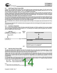
6.0
Clocking
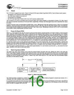
XTALOUT
(pin 1)
XTALIN
(pin 2)
to internal PLL
30 pF
30 pF
Figure 6-1. Clock Oscillator On-Chip Circuit
The XTALIN and XTALOUT are the clock pins to the microcontroller. The user can connect an external oscillator or a crystal to
these pins. When using an external crystal, keep PCB traces between the chip leads and crystal as short as possible (less than
2 cm). A 6-MHz fundamental frequency parallel resonant crystal can be connected to these pins to provide a reference frequency
for the internal PLL. The two internal 30-pF load caps appear in series to the external crystal and would be equivalent to a 15 pF
load. Therefore, the crystal must have a required load capacitance of about 15–18 pF. A ceramic resonator does not allow the
microcontroller to meet the timing specifications of full speed USB and therefore a ceramic resonator is not recommended with
these parts.
An external 6-MHz clock can be applied to the XTALIN pin if the XTALOUT pin is left open. Grounding the XTALOUT pin when
driving XTALIN with an oscillator does not work because the internal clock is effectively shorted to ground.
Document #: 38-08001 Rev. **
Page 15 of 48

 CYPRESS [ CYPRESS ]