FOR
FOR
CY7C63411/12/13
CY7C63511/12/13
CY7C63612/13
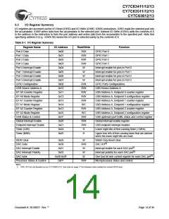
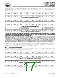
9.2
GPIO Configuration Port
Every GPIO port can be programmed as inputs with internal pull-ups, open drain outputs, and traditional CMOS outputs. In ad-
dition, the interrupt polarity for each port can be programmed. With positive interrupt polarity, a rising edge (“0” to “1”) on an input
pin causes an interrupt. With negative polarity, a falling edge (“1” to “0”) on an input pin causes an interrupt. As shown in the table
below, when a GPIO port is configured with CMOS outputs, interrupts from that port are disabled. The GPIO Configuration Port
register provides two bits per port to program these features. The possible port configurations are:
Port Configuration bits
Pin Interrupt Bit
Driver Mode
Resistive
Interrupt Polarity
11
10
10
01
00
X
0
-
CMOS Output
Open Drain
Open Drain
Open Drain
disabled
disabled
-
1
X
X
+ (default)
In “Resistive” mode, a 7-kΩ pull-up resistor is conditionally enabled for all pins of a GPIO port. The resistor is enabled for any pin
that has been written as a “1.” The resistor is disabled on any pin that has been written as a “0.” An I/O pin will be driven high
through a 7-kΩ pull-up resistor when a “1” has been written to the pin. Or the output pin will be driven LOW, with the pull-up dis-
abled, when a “0” has been written to the pin. An I/O pin that has been written as a “1” can be used as an input pin with an inte-
grated 7-kΩ pull-up resistor. Resistive mode selects a negative (falling edge) interrupt polarity on all pins that have the GPIO
interrupt enabled.
In “CMOS” mode, all pins of the GPIO port are outputs that are actively driven. The current source and sink capacity are roughly
the same (symmetric output drive). A CMOS port is not a possible source for interrupts.
A port configured in CMOS mode has interrupt generation disabled, yet the interrupt mask bits serve to control port direction. If
a port’s associated Interrupt Mask bits are cleared, those port bits are strictly outputs. If the Interrupt Mask bits are set then those
bits will be open drain inputs. As open drain inputs, if their data output values are ‘1’ those port pins will be CMOS inputs (HIGH
Z output).
In “Open Drain” mode the internal pull-up resistor and CMOS driver (HIGH) are both disabled. An I/O pin that has been written
as a “1” can be used as either a high-impedance input or a three-state output. An I/O pin that has been written as a “0” will drive
the output LOW. The interrupt polarity for an open drain GPIO port can be selected as either positive (rising edge) or negative
(falling edge).
During reset, all of the bits in the GPIO Configuration Register are written with “0.” This selects the default configuration: Open
Drain output, positive interrupt polarity for all GPIO ports.
7
6
5
4
3
2
1
0
Port 3
Config Bit 1
Port 3
Config Bit 0
Port 2
Config Bit 1
Port 2
Config Bit 0
Port 1
Config Bit 1
Port 1
Config Bit 0
Port 0
Config Bit 1
Port 0
Config Bit 0
Document #: 38-08027 Rev. **
Page 18 of 36

 CYPRESS [ CYPRESS ]