FOR
FOR
CY7C63411/12/13
CY7C63511/12/13
CY7C63612/13
10.0
DAC Port
VCC
Q1
Data
Internal
Data Bus
Out
Latch
14 KΩ
DAC Write
DAC
I/O Pin
4 bits
Isink
DAC
Isink
Register
ESD
Internal
Buffer
DAC Read
Interrupt
Enable
to Interrupt
Controller
Interrupt
Polarity
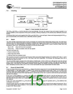
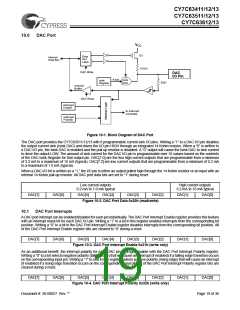
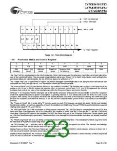
Figure 10-1. Block Diagram of DAC Port
The DAC port provides the CY7C63511/12/13 with 8 programmable current sink I/O pins. Writing a “1” to a DAC I/O pin disables
the output current sink (Isink DAC) and drives the I/O pin HIGH through an integrated 14 Kohm resistor. When a “0” is written to
a DAC I/O pin, the Isink DAC is enabled and the pull-up resistor is disabled. A “0” output will cause the Isink DAC to sink current
to drive the output LOW. The amount of sink current for the DAC I/O pin is programmable over 16 values based on the contents
of the DAC Isink Register for that output pin. DAC[1:0] are the two high current outputs that are programmable from a minimum
of 3.2 mA to a maximum of 16 mA (typical). DAC[7:2] are low current outputs that are programmable from a minimum of 0.2 mA
to a maximum of 1.0 mA (typical).
When a DAC I/O bit is written as a “1,” the I/O pin is either an output pulled high through the 14 Kohm resistor or an input with an
internal 14 Kohm pull-up resistor. All DAC port data bits are set to “1” during reset.
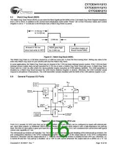
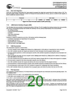
Low current outputs
0.2 mA to 1.0 mA typical
High current outputs
3.2 mA to 16 mA typical
DAC[7]
DAC[6]
DAC[5]
DAC[4]
DAC[3]
DAC[2]
DAC[1]
DAC[0]
Figure 10-2. DAC Port Data 0x30h (read/write)
10.1
DAC Port Interrupts
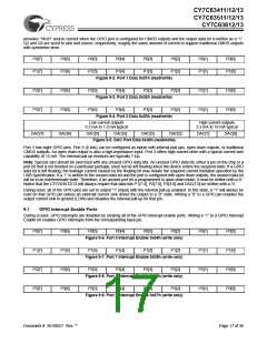
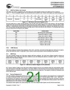
A DAC port interrupt can be enabled/disabled for each pin individually. The DAC Port Interrupt Enable register provides this feature
with an interrupt mask bit for each DAC I/O pin. Writing a “1” to a bit in this register enables interrupts from the corresponding bit
position. Writing a “0” to a bit in the DAC Port Interrupt Enable register disables interrupts from the corresponding bit position. All
of the DAC Port Interrupt Enable register bits are cleared to “0” during a reset.
DAC[7]
DAC[6]
DAC[5]
DAC[4]
DAC[3]
DAC[2]
DAC[1]
DAC[0]
Figure 10-3. DAC Port Interrupt Enable 0x31h (write only)
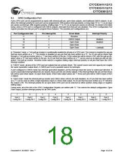
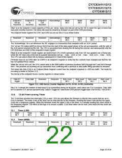
As an additional benefit, the interrupt polarity for each DAC pin is programmable with the DAC Port Interrupt Polarity register.
Writing a “0” to a bit selects negative polarity (falling edge) that will cause an interrupt (if enabled) if a falling edge transition occurs
on the corresponding input pin. Writing a “1” to a bit in this register selects positive polarity (rising edge) that will cause an interrupt
(if enabled) if a rising edge transition occurs on the corresponding input pin. All of the DAC Port Interrupt Polarity register bits are
cleared during a reset.
DAC[7]
DAC[6]
DAC[5]
DAC[4]
DAC[3]
DAC[2]
DAC[1]
DAC[0]
Figure 10-4. DAC Port Interrupt Polarity 0x32h (write only)
Document #: 38-08027 Rev. **
Page 19 of 36

 CYPRESS [ CYPRESS ]