FOR
FOR
CY7C63411/12/13
CY7C63511/12/13
CY7C63612/13
10.2
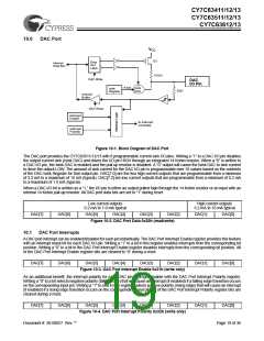
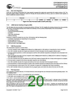
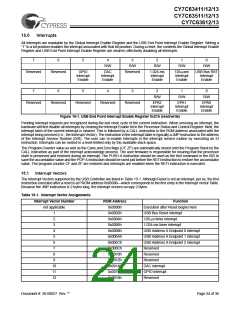
DAC Isink Registers
Each DAC I/O pin has an associated DAC Isink register to program the output sink current when the output is driven LOW. The
first Isink register (0x38h) controls the current for DAC[0], the second (0x39h) for DAC[1], and so on until the Isink register at
0x3Fh controls the current to DAC[7].
Reserved
Isink Value
Isink[2] Isink[1]
Figure 10-5. DAC Port Isink 0x38h to 0x3Fh (write only)
Isink[3]
Isink[0]
11.0
USB Serial Interface Engine (SIE)
The SIE allows the microcontroller to communicate with the USB host. The SIE simplifies the interface between the microcontroller
and USB by incorporating hardware that handles the following USB bus activity independently of the microcontroller:
• Bit stuffing/unstuffing
• Checksum generation/checking
• ACK/NAK
• Token type identification
• Address checking
Firmware is required to handle the rest of the USB interface with the following tasks:
• Coordinate enumeration by responding to set-up packets
• Fill and empty the FIFOs
• Suspend/Resume coordination
• Verify and select Data toggle values
11.1
USB Enumeration
The enumeration sequence is shown below:
1. The host computer sends a Setup packet followed by a Data packet to USB address 0 requesting the Device descriptor.
2. The USB Controller decodes the request and retrieves its Device descriptor from the program memory space.
3. The host computer performs a control read sequence and the USB Controller responds by sending the Device descriptor over
the USB bus.
4. After receiving the descriptor, the host computer sends a Setup packet followed by a Data packet to address 0 assigning a
new USB address to the device.
5. The USB Controller stores the new address in its USB Device Address Register after the no-data control sequence is complete.
6. The host sends a request for the Device descriptor using the new USB address.
7. The USB Controller decodes the request and retrieves the Device descriptor from the program memory.
8. The host performs acontrol read sequenceand theUSB Controllerrespondsbysending itsDevicedescriptor overtheUSBbus.
9. The host generates control reads to the USB Controller to request the Configuration and Report descriptors.
10.The USB Controller retrieves the descriptors from its program space and returns the data to the host over the USB.
11.2
PS/2 Operation
PS/2 operation is possible with the CY7C634XX/5XX/6XX series through the use of firmware and several operating modes. The
first enabling feature:
1. USB Bus reset on D+ and D− is an interrupt that can be disabled;
2. USB traffic can be disabled via bit 7 of the USB register;
3. D+ and D− can be monitored and driven via firmware as independent port bits.
Bits 5 and 4 of the Upstream Status and Control register are directly connected to the D+ and D− USB pins of the CY7C634XX/
5XX/6XX. These pins constantly monitor the levels of these signals with CMOS input thresholds. Firmware can poll and decode
these signals as PS/2 clock and data.
Bits [2:0] defaults to ‘000’ at reset which allows the USB SIE to control output on D+ and D−. Firmware can override the SIE and
directly control the state of these pins via these 3 control bits. Since PS/2 is an open drain signaling protocol, these modes allow
all 4 PS/2 states to be generated on the D+ and D− pins
Document #: 38-08027 Rev. **
Page 20 of 36

 CYPRESS [ CYPRESS ]