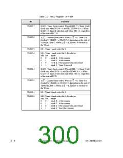
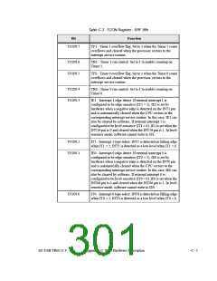
Table C-2. TMOD Register - SFR 89h
Bit
Function
TMOD.7
GATE - Timer 1 gate control. When GATE = 1, Timer 1 will
clock only when INT1# = 1 and TR1 (TCON.6) = 1. When
GATE = 0, Timer 1 will clock only when TR1 = 1, regardless
of the state of INT1#.
TMOD.6
- Counter/Timer select. When
= 0, Timer 1 is
C/ T
clocked by CLK24/4 or CLK24/12, depending on the state of
C/ T
T1M (CKCON.4). When
the T1 pin.
= 1, Timer 1 is clocked by
C/ T
TMOD.5
TMOD.4
M1 - Timer 1 mode select bit 1.
M0 - Timer 1 mode select bit 0, decoded as:
M1 M0 Mode
0
0
1
1
0
1
0
1
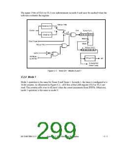
Mode 0 : 13-bit counter
Mode 1 : 16-bit counter
Mode 2 : 8-bit counter with auto-reload
Mode 3 : Timer 1 stopped
TMOD.3
TMOD.2
GATE - Timer 0 gate control, When GATE = 1, Timer 0 will
clock only when INT0 = 1 and TR0 (TCON.4) = 1. When
GATE = 0, Timer 0 will clock only when TR0 = 1, regardless
of the state of INT0.
- Counter/Timer select. When
= 0, Timer 0 is
C/ T
C/ T
clocked by CLK24/4 or CLK24/12, depending on the state of
T0M (CKCON.3). When
the T0 pin.
= 1, Timer 0 is clocked by
C/ T
TMOD.1
TMOD.0
M1 - Timer 0 mode select bit 1.
M0 - Timer 0 mode select bit 0, decoded as:
M1 M0 Mode
0
0
1
1
0
1
0
1
Mode 0 : 13-bit counter
Mode 1 : 16-bit counter
Mode 2 : 8-bit counter with auto-reload
Mode 3 : Two 8-bit counters
C - 4
Appendix C: 8051 Hardware Description
EZ-USB TRM v1.9

 CYPRESS [ CYPRESS ]