T0M (or T1M)
Divide by 12
Divide by 4
0
C/T
0
CLK24
TL0 (or TL1)
1
7
0
RELOAD
1
CLK
T0 (or T1) pin
TR0 (or TR1)
TH0 (or TH1)
0
7
GATE
TF0 (or TF1)
INT
INT0# pin
(or INT1# pin)
To Serial Port
(Timer 1 only)
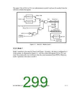
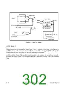
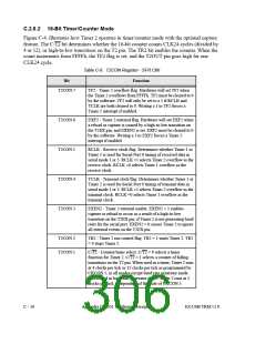
Figure C-2. Timer 0/1 - Mode 2
C.2.5 Mode 2
Mode 2 operation is the same for Timer 0 and Timer 1. In mode 2, the timer is configured as
an 8-bit counter, with automatic reload of the start value. The LSB register (TL0 or TL1) is the
counter and the MSB register (TH0 or TH1) stores the reload value.
As illustrated in Figure C-2., mode 2 counter control is the same as for mode 0 and mode 1.
However, in mode 2, when TLn increments from FFh, the value stored in THn is reloaded into
TLn.
C - 6
Appendix C: 8051 Hardware Description
EZ-USB TRM v1.9

 CYPRESS [ CYPRESS ]