C.2.1 803x/805x Compatibility
The implementation of the timers/counters is similar to that of the Dallas Semiconductor
DS80C320. Table C-1. summarizes the differences in timer/counter implementation between
the Intel 8051, the Dallas Semiconductor DS80C320, and the 8051 core.
Table C-1. Timer/Counter Implementation Comparison
Dallas
DS80C320
Feature
Intel 8051
8051
Number of timers
2
3
3
Timer 0/1 overflow
not
not
T0OUT, T1OUT
available as output signals
implemented implemented (one CLK24 pulse)
Timer 2 output enable
n/a
n/a
n/a
implemented not implemented
implemented not implemented
Timer 2 downcount enable
Timer 2 overflow available
as output signal
implemented T2OUT
(one CLK24 pulse)
C.2.2 Timers 0 and 1
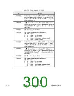
Timers 0 and 1 each operate in four modes, as controlled through the TMOD SFR (Table C-2.)
and the TCON SFR (Table C-3.). The four modes are:
•
•
•
•
13-bit timer/counter (mode 0)
16-bit timer/counter (mode 1)
8-bit counter with auto-reload (mode 2)
Two 8-bit counters (mode 3, Timer 0 only)
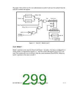
C.2.3 Mode 0
Mode 0 operation, illustrated in Figure C-1., is the same for Timer 0 and Timer 1. In mode 0,
the timer is configured as a 13-bit counter that uses bits 0-4 of TL0 (or TL1) and all 8 bits of
TH0 (or TH1). The timer enable bit (TR0/TR1) in the TCON SFR starts the timer. The C/T bit
selects the timer/counter clock source, CLK24 or the T0/T1 pins.
The timer counts transitions from the selected source as long as the GATE bit is 0, or the
GATE bit is 1 and the corresponding interrupt pin (INT0# or INT1#) is 1.
When the 13-bit count increments from 1FFFh (all ones), the counter rolls over to all zeros,
the TF0 (or TF1) bit is set in the TCON SFR, and the T0OUT (or T1OUT) pin goes high for
one clock cycle.
C - 2
Appendix C: 8051 Hardware Description
EZ-USB TRM v1.9

 CYPRESS [ CYPRESS ]