GMSK Packet Data Modem and RF Transceiver
CMX990
5.4
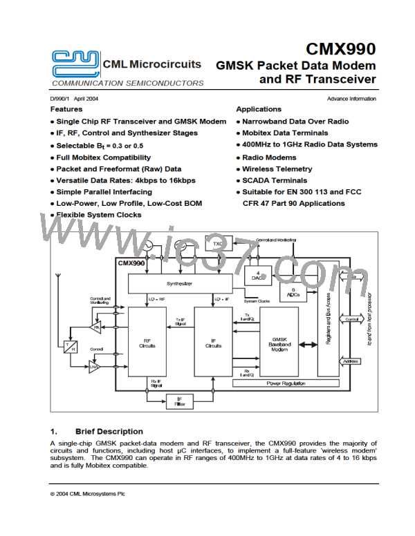
Synthesiser
Two integer-N synthesisers are provided, one as the main RF synthesiser (Main PLL), which provides the
tuneable frequency to enable channel selection, and the other (Aux PLL) for the generation of lower
frequency for mixing from IF to baseband. These two synthesisers are fully programmable, via the
processor interface, to any frequency in the range 600 MHz to 2 GHz and 150 MHz to 250 MHz
respectively.
Both the synthesised frequencies are internally divided down. The main RF frequency is divided by two
for use in the offset loop in the transmitter and also for the image reject mixer in the receiver. Note that,
in order to obtain quadrature signals for the IR mixer, both the rising and falling edges of the VCO
generated signal are used; it is important, therefore, that the VCO produce a waveform that is as close as
possible to a mark to space ratio of one. The second synthesiser is optionally divided by 2 or 4 for the
transmitter and divided by 4 for the receiver.
Both synthesisers are phase locked loops (PLLs) and utilise external VCOs and loop filters. The phase
noise of the VCOs should be adequate for the application with particular attention paid to the
performance of the main VCO. It will be noted that as the CMX990 includes an internal divide-by-two in
the LO path the PLL phase noise will be improved by approximately 6dB. The loop filters will need to be
designed as required based on switching bandwidths, VCO gain etc. The CMX990 phase detectors are of
the phase-frequency type with a high impedance charge pump output requiring just passive components
in the loop filter. As a result standard design equations for a type II PLL can be used to select loop filter
components. Lock detect functions are built in to each synthesiser and the status reported to the host
processor. In particular, a transition to out-of-lock can be detected and communicated via an interrupt to
the processor if required; this can be important to ensure that the transmitter cannot falsely transmit into
other bands in the event of a fault condition arising.
The minimum step size is also programmable by setting the reference division ratio; to minimise the
effects of phase noise this should be kept as high as possible, particularly on the main RF synthesiser.
For Mobitex, the maximum this can be set to is 25 kHz as this is governed by the 12.5 kHz channel
spacing and the subsequent divide-by-2 of the generated frequency. Note that if it is required to select a
frequency that is 6.25 kHz offset from a convenient division of the main frequency (although still with
12.5 kHz channel spacings), it is better to keep the step size at 25 kHz but slightly offset the reference
oscillator. In this way the phase noise and lock time performance will not be compromised.
Each synthesiser is set up using two registers, an ‘N’ register that sets the division value of the input
reference frequency to the comparison frequency (step size), and an ‘M’ register that sets the division of
the required synthesised frequency from the external VCO to the comparison frequency.
In the main PLL the VCO frequency is pre-scaled by 2 prior to being divided by N there therefore there is
a factor of 2 in the formula that yields a required synthesised frequency (Fs) such that:
Fs = (2 x N / M) x FREF
For the aux PLL the formula is:
Fs = ( N / M ) x FREF
where FREF is the reference oscillator frequency
ã 2004 CML Microsystems Plc
57
D/990/1

 CMLMICRO [ CML MICROCIRCUITS ]