GMSK Packet Data Modem and RF Transceiver
CMX990
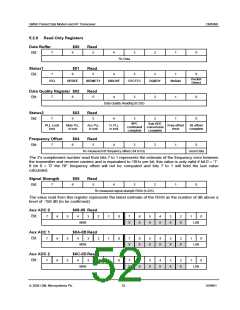
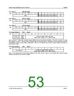
Aux ADC 3
Bit:
$0E-0F Read
7
6
6
6
5
5
5
4
3
2
2
2
1
1
1
0
0
0
7
6
5
4
3
2
1
1
1
0
0
0
MSB
X
X
X
X
X
X
LSB
LSB
Aux ADC 4
Bit:
$10-11 Read
7
4
3
7
6
5
4
3
2
MSB
X
X
X
X
X
X
Aux ADC 5
Bit:
$12-13 Read
7
4
3
7
6
5
4
3
2
MSB
X
X
X
X
X
X
LSB
0
Analogue Setup 1
$18
Read
7
6
5
4
3
2
1
Bit:
Channel
filter
overflow
Coarse Rx I offset, '10000' = Mid value
'00000' = Max -ve offset, '11111' = Max +ve offset
X
Bit 6 is set to '1' when the receive channel filters have a numerical overflow. This bit is reset to '0' after
this register is read. This bit does not generate an interrupt and is intended for test purposes only for
evaluating custom receive filter coefficients. Bits 5 to 0 indicate the current coarse offset correction in
the receive I path.
Analogue Setup 2
$19
Read
7
6
5
4
3
2
1
0
Bit:
Coarse Rx Q offset, '10000' = Mid value
'00000' = Max -ve offset, '11111' = Max +ve offset
AGC setting 0-3
Bits 7 to 6 indicate the current gain setting of the AGC circuit. Bits 5 to 0 indicate the current coarse
offset correction in the receive Q path.
ã 2004 CML Microsystems Plc
53
D/990/1

 CMLMICRO [ CML MICROCIRCUITS ]