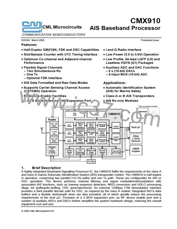
AIS Baseband Processor
CMX910
Interrupt register b7: Tx FIFO Trigger
This bit is connected directly to Tx_Status b7, and goes high to indicate that the Tx FIFO fill level
has dropped below a user-defined threshold (Tx_Status[13-8] ≤ Tx_FIFO_Threshold[4-0]). Note
that this bit is level triggered, it does not get cleared by being read.
Interrupt register b6: FSK FIFO Trigger
This bit is connected directly to FSK_Status b7, and goes high to indicate that the FSK FIFO fill
level has exceeded a user-defined threshold (FSK_Status[13-8] > FSK_FIFO_Threshold[4-0]).
Note that this bit is level triggered, it does not get cleared by being read.
Interrupt register b5: Rx2 FIFO Trigger
This bit is connected directly to Rx2_Status b7, and goes high to indicate that the Rx2 FIFO fill
level has exceeded a user-defined threshold (Rx2_Status[13-8] > Rx2_FIFO_Threshold[4-0]).
Note that this bit is level triggered, it does not get cleared by being read.
Interrupt register b4: Rx1 FIFO Trigger
This bit is connected directly to Rx1_Status b7, and goes high to indicate that the Rx1 FIFO fill
level has exceeded a user-defined threshold (Rx1_Status[13-8] > Rx1_FIFO_Threshold[4-0]).
Note that this bit is level triggered, it does not get cleared by being read.
Interrupt register b3: Tx Done
This bit goes high to indicate that a transmit operation has completed or that an error condition
has occurred. This bit gets cleared automatically after being read.
Interrupt register b2: Rx2 Burst Available
This bit goes high to indicate that an AIS packet is available in channel Rx2 (AIS burst mode
only). This bit gets cleared automatically after being read.
Interrupt register b1: Rx1 Burst Available
This bit goes high to indicate that an AIS packet is available in channel Rx1 (AIS burst mode
only). This bit gets cleared automatically after being read.
Interrupt register b0: Nudge Done
This bit goes high to indicate that a requested slot/sample nudge operation has been completed.
This bit gets cleared automatically after being read.
Interrupt_Enable register: 16-bit write only.
C-BUS Address $81
All bits cleared to 0 on reset.
15
14
13
12
11
10
9
8
7
6
5
4
3
2
1
0
Bit:
IRQN IRQN IRQN IRQN IRQN IRQN IRQN IRQN IRQN IRQN IRQN IRQN IRQN IRQN IRQN IRQN
En 15 En 14 En 13 En 12 En 11 En 10 En 9 En 8 En 7 En 6 En 5 En 4 En 3 En 2 En 1 En 0
Interrupt_Enable register b15-0: Interrupt Enable Bits
The setting in this register determines which of the bits in the Interrupt register can cause a host
µC interrupt – setting a bit high in the Interrupt_Enable register allows the associated bit in the
Interrupt register to drive the IRQN pin low. The Interrupt_Enable register can be written at any
time, and can be used to enable or disable any combination of the sixteen interrupt sources. Note:
the value written to the Interrupt_Enable register does not affect the contents of the Interrupt
register.
IMPORTANT NOTICE: If an interrupt occurs whilst the Interrupt register is being read by the host
controller, there is a possibility that the new interrupt may be lost. To minimise the chances of this
happening, it is recommended that the Interrupt register should only be read when the IRQN pin
goes active (the interrupt register should NOT be polled). It is further recommended that when
the host microcontroller is waiting for an interrupt, a timeout routine is implemented.
© 2009 CML Microsystems Plc
47
D/910/6

 CMLMICRO [ CML MICROCIRCUITS ]