AIS Baseband Processor
CMX910
5.12
Special Command Interface
The Special Command Interface allows the CMX910 to perform the special tasks defined below. The
interface comprises two 16-bit write registers and a 16-bit read register for data transfers and an 8-bit
write register which is used to instruct the CMX910 which special command to perform.
When executing a special command that requires data to be transferred to the CMX910, the data must
first be written to the SPC_In0/1 registers, then the command code should be written to the
Special_Command register. The act of writing to the Special_Command register causes the CMX910 to
begin processing the command, during which time the data in SPC_In0, SPC_In1 and Special_Command
should not be changed. When the special command has completed, the “Special Command Done” bit in
the Interrupt register goes high and the Special_Command register gets cleared, and the returned data (if
any) will be available in SPC_Out0. The CMX910 is then ready to accept another special command.
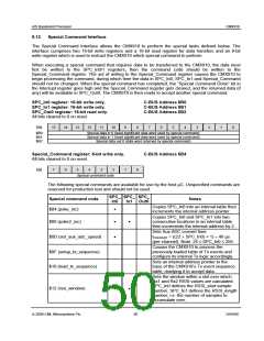
SPC_In0 register: 16-bit write only.
SPC_In1 register: 16-bit write only.
SPC_Out0 register: 16-bit read only.
All bits cleared to 0 on reset.
C-BUS Address $B0
C-BUS Address $B1
C-BUS Address $B2
15
14
13
12
11
10
9
8
7
6
5
4
3
2
1
0
Bit:
$B0:
$B1:
$B2:
Special data in 0 (least significant data word used by special command)
Special data in 1 (most significant data word used by special command)
Special data out 0 (data word returned by special command)
Special_Command register: 8-bit write only.
C-BUS Address $B4
All bits cleared to 0 on reset.
7
6
5
4
3
2
1
0
Bit:
Special command code
The following special commands are available for use by the host µC. Unspecified commands are
reserved for production test and should not be used.
SPC_ SPC_ SPC_
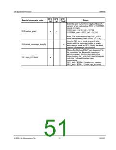
Special command code
Notes
In0
In1 Out0
Copies SPC_In0 into an internal table then
increments the internal address pointer.
$04 (poke_inc)
•
Copies SPC_In0 and SPC_In1 into two
consecutive locations in an internal table
then increments the internal address by 2.
Sets Aux ADC convert time:
tCONVERT = ((22 × SPC_In0) + 1) ÷ 48 µs
$08 (poke2_inc)
•
•
•
$0D (set_aux_adc_speed)
$0F (setup_tx_sequence)
$10 (load_tx_sequence)
(per channel). Note: 24 ≤ SPC_In0 ≤ 256.
Causes the CMX910 to process the
previously loaded table of Tx events and
configure its internal Tx logic accordingly.
Sets an internal address pointer to the
base of the CMX910’s Tx event sequence
table, readying it to accept data.
Sets the window within a slot over which
Rx1 and Rx2 RSSI values are calculated.
SPC_In0 defines the RSSI_start sample
number, SPC_In1 defines the RSSI_length
number, i.e. the number of samples to
accumulate over.
$12 (rssi_window)
•
•
© 2009 CML Microsystems Plc
50
D/910/6

 CMLMICRO [ CML MICROCIRCUITS ]