AIS Baseband Processor
CMX910
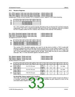
Rx1/Rx2/FSK_Status register b14: Underflow
These bits get set high if the µC attempts to read from the associated FIFO when it is already
empty. The Rx1/Rx2/FSK underflow bits get cleared as soon as the associated status register is
read.
Note: Each receive channel status register has b15 and b14 ORed together for the purpose of
generating an interrupt.
Rx1/Rx2/FSK_Status register b13-8: FIFO Fill Level
This shows how many bytes are in the associated FIFO. The number will be in the range 0 to 32.
Rx1/Rx2/FSK_Status register b7: FIFO Trigger
These bits will be high if the associated FIFO fill level is greater than the threshold level, i.e.
These bits can generate an interrupt.
•
•
•
Rx1 FIFO Trigger is set high if (Rx1_Status[13-8] > Rx1_FIFO_Threshold[4-0])
Rx2 FIFO Trigger is set high if (Rx2_Status[13-8] > Rx2_FIFO_Threshold[4-0])
FSK FIFO Trigger is set high if (FSK_Status[13-8] > FSK_FIFO_Threshold[4-0])
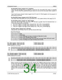
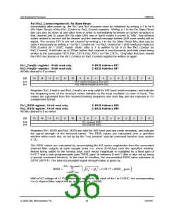
Rx1/Rx2_Status register b2-0: AIS State
Indicates the current state of the Rx1 and Rx2 channel (AIS only).
b2
b1
b0
0
0
0
0
1
1
0
0
1
1
0
0
0
1
0
1
0
1
Idle
Receiving
Error: Message too long or missing end flag (burst mode)
Error: CRC mismatch (burst mode)
Error: New frame header found but both message buffers full (burst mode)
Error: End flag not on byte boundary (burst mode)
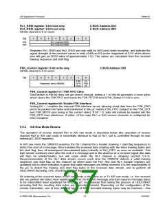
Rx1_Slot register: 16-bit read only.
Rx2_Slot register: 16-bit read only.
All bits cleared to 0 on reset.
C-BUS Address $33
C-BUS Address $43
15
14
13
12
11
10
9
8
7
6
5
4
3
2
1
0
Bit:
$33:
$43:
Slot number in which a valid training sequence + start flag was detected in channel Rx1
Slot number in which a valid training sequence + start flag was detected in channel Rx2
Rx1_Sample register: 16-bit read only.
Rx2_Sample register: 16-bit read only.
All bits cleared to 0 on reset.
C-BUS Address $34
C-BUS Address $44
15
14
13
12
11
10
9
8
7
6
5
4
3
2
1
0
Bit:
$34:
$44:
Sample number in which a valid training sequence + start flag was detected in channel Rx1
Sample number in which a valid training sequence + start flag was detected in channel Rx2
When receiving an AIS message on the Rx1 channel, the CMX910 writes the time at which the
last bit of the start flag is detected into the Rx1_Slot and Rx1_Sample registers (this is only done
if a the start flag is preceded by a valid training sequence). The Rx2_Slot and Rx2_Sample
registers perform the same function for the Rx2 channel. Note: the delay through the CMX910’s
internal filters mean that the reported Slot/Sample number will be approximately 52 sample
periods (10.4 bit periods) later than the arrival time of the last bit of the start flag at the device
pins.
© 2009 CML Microsystems Plc
34
D/910/6

 CMLMICRO [ CML MICROCIRCUITS ]