AIS Baseband Processor
CMX910
SPC
_In1
SPC
_In0
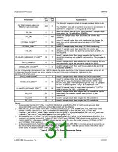
Parameter
Explanation
The transmit sequence starts at sample number 500 in a slot.
Tx_Start sample value and
ENAB0-5 pin reset state
500
0
The ENAB0-5 pins will be set to 0 on a reset or a command to
start the Tx sequence, i.e. they are all active high.
After the initial 4 sample delay, insert another 5 sample delay
then assert the TX control line (ENAB4).
TX_ON
RF_ON
2
1
5
Insert 790 sample delay then assert the RF control line
(ENAB0).
790
Insert 20 sample delay then start monitoring the chosen Rx
input for a signal which will cause an abort (if CSTDMA
enabled).
CSTDMA_START1,3
CSTDMA_END1,3
PA_ON
5
6
3
20
32
15
Insert 32 sample delay then stop CSTDMA monitoring.
Insert 15 sample delay then assert the PA control line
(ENAB5). At this point, the three Rx control lines (ENAB1-3)
are negated.
Insert 1 sample delay then place a marker for the point at
which the sequence will restart if a consecutive Tx message is
needed.
CHAINED_MESSAGE_START1,2
14
1
Insert 6 sample delay then initiate the DAC0 ramp-up (for AIS,
the transmitted signal will be carrier only at this point)
DAC0_RAMPUP
4
7
6
8
Insert 8 sample delay then start feeding data to the transmit
modulator and filters.
MODULATE_START1,2
At this point during a transmission the CMX910 feeds the entire message to the transmit modulator bit-by-bit. All
subsequent transmit events are timed relative to the end of the last message bit, indicated by the
MODULATE_END event.
DAC0_RAMPDOWN4
9
1
Insert 1 sample delay then initiate the DAC0 ramp-down.
Insert 10 sample delay then define the “end-of-modulation”
point (“B” in Figure 10). Between MODULATE_START and
MODULATE_END there are (message bits × 5) +46 samples
for AIS, or (message bits × 40) + 46 samples for FSK.
MODULATE_END1,2
8
10
Insert 30 sample delay. If more data is present in Tx_FIFO,
chain a second (or third…) message on.
CHAINED_MESSAGE_END1,2
PA_OFF
15
10
30
6
Insert 6 sample delay then negate the PA control line. At the
same time, the three Rx control lines (ENAB1-3) are
reasserted.
TX_OFF
RF_OFF
11
12
7
8
Insert 7 sample delay then negate the TX control line.
Insert 8 sample delay then negate the RF control line.
Notes:
1. It is essential that the CSTDMA, CHAINED_MESSAGE and MODULATE START events precede their
associated END events, otherwise undesirable results will be obtained.
2. MODULATE_START must come after CHAINED_MESSAGE_START and MODULATE_END must come
before CHAINED_MESSAGE_END for consecutive messages to work. MODULATE_START and
CHAINED_MESSAGE_START must appear in the first group of eight timed events, MODULATE_END and
CHAINED_MESSAGE_END must appear in the final group of six.
3. It is intended that CSTDMA only operates in the period prior to the actual on-air transmission of the first in a
sequence of chained messages. Both CSTDMA_START and CSTDMA_END should come before PA_ON and
DAC0_RAMPUP, otherwise CSTDMA will not operate correctly. Also, the delay between CSTDMA_START
and CSTDMA_END must be ≥ 7.
4. In this example DAC0_RAMPDOWN is specified before MODULATE_END in the last group of six events, so
the DAC0 ramp-down begins prior to the MODULATE_END point – with the values shown, the DAC0 ramp-
down starts 10 samples before MODULATE_END.
Table 2 Example Tx Event Sequence Setup
© 2009 CML Microsystems Plc
31
D/910/6

 CMLMICRO [ CML MICROCIRCUITS ]