TDMA Digital Radio Processor
CMX7161
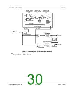
7.10 External Interfaces
The CMX7161 provides additional external interfaces to assist with controlling the radio transmitter and
receiver. These include:
Four auxiliary ADCs
Four auxiliary DACs, one of which may be configured as a RAMDAC to control PA ramping
An SPI Thru-Port port which may be used to control radio ICs with C-BUS/SPI interfaces
Four GPIO pins which may be used for Tx/Rx switching, LNA off and general device control.
7.10.1 GPIO Pin Operation
The CMX7161 provides four GPIO pins, each of which can be configured independently as
automatic/manual, input/output and rising/falling (with the exception of the combination automatic + input
function which is only allowed for GPIOA).
Pins that are automatic outputs become part of a transmit sequence and will automatically switch, along
with the RAMDAC – AuxDAC1 (if it is configured as automatic), during the course of a burst. Pins that are
manual are under direct user control. When automatic, a rising or a falling event at the start or end of
transmission will cause the specified GPIO to be switched high or low accordingly.
GPIOA may be configured as an automatic input. This means that any attempted transmission will wait
until GPIOA input is high (if rising is selected) or low (if falling is selected).
Note: On the DE9943 Evaluation Kit, GPIOB is used as Tx Enable; GPIOA is used as Rx Enable.
See:
GPIO Control - $64, write
GPIO Input - $79, read.
7.10.2 Auxiliary ADC Operation
The inputs to the four Auxiliary ADCs can be independently routed from any of four dedicated AuxADC
input pins or from the two main I/Q inputs. If not required the AuxADCs can be disabled to save power.
BIAS in the VBIAS Control - $B7, write register must be enabled for Auxiliary ADC operation.
Averaging can be applied to the ADC readings by selecting the relevant bits in the AuxADC1-4 Control -
$51 to $54, write registers. This is a rolling average in which a proportion of the current sample is
combined at each step with the previous average value. The proportion is determined by the value of the
average counter in the AuxADC1-4 Control - $51 to $54, write registers. Setting the average counter to
zero disables the averager; an value of 1 means that 50% of the current sample will be applied; a value of
2 gives 25%, 3 gives 12.5%, continuing up to the maximum useful value of 11 giving 0.0488%.
High and low thresholds may be independently applied to both ADC channels (the comparison is applied
after averaging, if this is enabled) and an IRQ generated when an input exceeds the high or low threshold,
or on every sample as required. The thresholds are programmed via the AuxADC1-4 Threshold - $55 to
$58, write register.
Auxiliary ADC data is read back in the AuxADC1-4 Read - $71 to $74, read registers and includes the
threshold status as well as the actual conversion data (subject to averaging, if enabled).
The AuxADC sample rate is selected using:
AuxADC1-4 Control - $51 to $54, write
AuxADC1-4 Threshold - $55 to $58, write
AuxADC1-4 Read - $71 to $74, read
VBIAS Control - $B7, write.
2013 CML Microsystems Plc
Page 28
D/7161_FI-1.0/4

 CMLMICRO [ CML MICROCIRCUITS ]