CS5525 CS5526
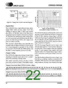
VA+
VD+
20 pF
500 k
Ω
XOUT
CS5525
CS5526
32.768 kHz
XIN
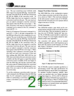
Figure 18. Tuning Fork Crystal Connection Diagram
Digital Filter
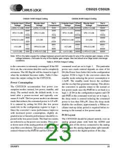
The CS5525/26 have eight different linear phase
digital filters which set the output word rates
(OWRs) as stated in Table 2. These rates assume
that XIN is 32.768 kHz. Each of the filters has a
magnitude response similar to that shown in Figure
19. The filters are optimized to settle to full accura-
cy every conversion and yield better than 80 dB re-
jection for both 50 and 60 Hz with output word
rates at or below 15.0 Hz.
Figure 19. Filter Response
(Normalized to Output Word Rate = 1)
first followed by the rest of the data bits in descend-
ing order. For the CS5525 the last byte is composed
of bits D7-D4, which are always logic 1; D3-D2,
which are always logic 0; and bits D1-D0 which are
the two flag bits. For the CS5526 the last byte in-
cludes data bits D7-D4, D3-D2 which are always
logic 0 and the two flag bits.
The converter’s digital filters scale with XIN. For
example with an output word rate of 15 Hz, the fil-
ter’s corner frequency is typically 12.7 Hz. If XIN
is increased to 64.536 kHz the OWR doubles and
the filter’s corner frequency moves to 25.4 Hz.
The OF (Overrange Flag) bit is set to a logic 1 any
time the input signal is: 1) more positive than posi-
tive full scale, 2) more negative than zero (unipolar
mode), 3) more negative than negative full scale
(bipolar mode). It is cleared back to logic 0 when-
ever a conversion word occurs which is not over-
ranged.
Output Coding
The CS5525/26 output data in binary format when
operating in unipolar mode and in two's comple-
ment when operating in bipolar mode.
The OD (Oscillation Detect) bit is set to a logic 1 any
time that an oscillatory condition is detected in the
modulator. This does not occur under normal oper-
ating conditions, but may occur whenever the input
The output conversion word is 24 bits, or three
bytes long, as shown in Table 5. The MSB is output
Output Conversion Data CS5525 (16 bits + flags)
D23 D22 D21 D20 D19 D18 D17 D16 D15 D14 D13 D12 D11 D10 D9 D8 D7 D6 D5 D4 D3 D2 D1 D0
MSB 14 13 12 11 10 LSB OD OF
9
8
7
6
5
4
3
2
1
1
1
1
1
0
0
Output Conversion Data CS5526 (20 bits + flags)
D23 D22 D21 D20 D19 D18 D17 D16 D15 D14 D13 D12 D11 D10 D9 D8 D7 D6 D5 D4 D3 D2 D1 D0
MSB 18 17 16 15 14 13 12 11 10
9
8
7
6
5
4
3
2
1
LSB
0
0
OD OF
Table 5. Data Conversion Word
22
DS202F3

 CIRRUS [ CIRRUS LOGIC ]