CS5525 CS5526
sion. The user would then issue 8 SCLKs (with
SDI = logic 0) to clear the SDO flag. Upon the fall-
ing edge of the 8th SCLK, the SDO pin will present
the first bit (MSB) of the conversion word. 24
SCLKs (high, then low) are required to read the
conversion word from the port. The user must not
give an explicit command to read the conversion
data register when the PF bit is set to logic 1. The
data conversion word must be read before a new
command can be entered (if the SC command is
used with PF = 1).
Output Word Rate Selection
The WR2-WR0 bits of the configuration register
set the output conversion word rate of the convert-
ers as shown in Table 2. The word rates indicated
in the table assume a master clock of 32.768 kHz.
Upon reset the converters are set to operate with an
output word rate of 15.0 Hz.
Clock Generator
The CS5525/26 include a gate which can be con-
nected with an external crystal to provide the master
clock for the chips. They are designed to operate us-
ing a low-cost 32.768 kHz “tuning fork” type crys-
tal. The 32.768 kHz crystal should be connected as
shown in Figure 18. Lead lengths should be mini-
mized to reduce stray capacitance.
If the CC (Continuous Conversion) command is is-
sued (CC = 1, CB =1, all other command bits = 0)
the SDO pin will go low at the completion of a con-
version. The user would then issue 8 SCLKs (with
SDI = logic 0) to clear the SDO flag. Upon the fall-
ing edge of the 8th SCLK, the SDO pin will present
the first bit (MSB) of the conversion word. 24
SCLKs (high, then low) are required to read the
conversion word from the port. The user must not
give an explicit command to read the conversion
data register when the PF bit is set to logic 1. When
operating in the continuous conversion mode, the
user need not read every conversion. If the user
does nothing after SDO falls, SDO will rise one
XIN clock cycle before the next conversion word is
available and then fall again to signal that another
conversion word is available. If the user begins to
clear the SDO flag and read the conversion data,
this action must be finished before the conversion
cycle which is occurring in the background is com-
plete if the user wants to be able to read the new
conversion data.
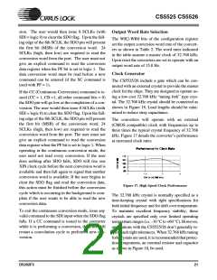
The converters will operate with an external
(CMOS compatible) clock with frequencies up to
three times the typical crystal frequency of 32.768
kHz. Figure 17 details the converter’s performance
at increased clock rates.
Figure 17. High Speed Clock Performance
The 32.768 kHz crystal is normally specified as a
time-keeping crystal with tight specifications for
both initial frequency and for drift over temperature.
To maintain excellent frequency stability, these
crystals are specified only over limited operating
temperature ranges (i.e. -10 °C to +60 °C). However,
applications with the CS5525/26 don’t generally re-
quire such tight tolerances. When 32.768 kHz tuning
fork crystals are used, it is recommended that protec-
tion components, an external resistor and capacitor
as shown in Figure 18, be used.
To exit the continuous conversion mode, issue any
valid command to the SDI input when the SDO flag
falls. If a CC command is issued to the converter
while it is performing a conversion, the filter will
restart a convolution cycle to perform a new con-
version.
DS202F3
21

 CIRRUS [ CIRRUS LOGIC ]