TSC2005
www.ti.com
SBAS379–DECEMBER 2006
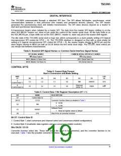
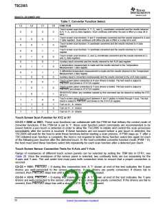
Table 7. Converter Function Select
C3
C2
C1
C0
FUNCTION
Touch screen scan function: X, Y, Z1, and Z2 coordinates converted and the results returned
0
0
0
0
to X, Y, Z1, and Z2 data registers. Scan continues until either the pen is lifted or a stop bit is
sent.
Touch screen scan function: X and Y coordinates converted and the results returned to X and
Y data registers. Scan continues until either the pen is lifted or a stop bit is sent.
0
0
0
0
0
0
0
1
1
1
0
1
Touch screen scan function: X coordinate converted and the results returned to X data
register.
Touch screen scan function: Y coordinate converted and the results returned to Y data
register.
Touch screen scan function: Z1 and Z2 coordinates converted and the results returned to Z1
and Z2 data registers.
0
0
0
1
1
1
0
0
1
0
1
0
Auxiliary input converted and the results returned to the AUX data register.
A temperature measurement is made and the results returned to the Temperature
Measurement 1 data register.
A differential temperature measurement is made and the results returned to the Temperature
Measurement 2 data register.
0
1
1
1
0
0
1
0
0
1
0
1
Auxiliary input is converted continuously and the results returned to the AUX data register.
Touch screen panel connection to X-axis drivers is tested. The test result is output to
PINTDAV and shown in STATUS register.
Touch screen panel connection to Y-axis drivers is tested. The test result is output to
PINTDAV and shown in STATUS register.
1
1
1
0
0
1
1
1
0
0
1
0
RESERVED (Note: any condition caused by this command can be cleared by setting the STS
bit to 1).
Touch screen panel short-circuit (between X and Y plates) is tested through Y-axis. The test
result is output to PINTDAV and shown in the STATUS register.
1
1
1
1
1
1
0
1
1
1
0
1
Turn on X+, X– drivers
Turn on Y+, Y– drivers
Turn on Y+, X– drivers
Touch Screen Scan Function for XYZ or XY
C3-C0 = 0000 or 0001: These scan functions can collaborate with the PSM bit that defines the control mode of
converter functions. If the PSM bit is set to '1', these scan function select commands are recommended to be
issued before a pen touch is detected in order to allow the TSC2005 to initiate and control the scan processes
immediately after the screen is touched. If these functions are not issued before a pen touch is detected, the
TSC2005 will wait for the host to write these functions before starting a scan process. If PSM stays as '1' after a
TSC-initiated scan function is complete, the host is not required to write these function select bits again for each
of the following pen touches after the detected touch. In the host-controlled converter function mode (PSM = 0),
the host must send these functions select bits repeatedly for each scan function after a detected pen touch.
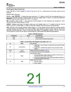
Touch Screen Sensor Connection Tests for X-Axis and Y-Axis
Range of resistances of different touch screen panels can be selected by setting the TBM bits in CFR1; see
Table 20. Once the resistance of the sensor panel is selected, two continuity tests are run separately for the
X-axis and Y-axis. The unit under test must pass both connection tests to ensure that a proper connection is
secured.
C3-C0 = 1001: PINTDAV = 0 during this connection test. A '1' shown at end of the test indicates the X-axis
drivers are well-connected to the sensor; otherwise, X-axis drivers are poorly connected. If drivers fail to
connect, then PINTDAV stays low until a stop bit (STS set to '1') is issued.
C3-C0 = 1010: PINTDAV = 0 during this connection test. A '1' shown at end of the test indicates the Y-axis
drivers are well-connected to the sensor; otherwise, Y-axis drivers are poorly connected. If the drivers are fail to
connect, then PINTDAV stays low until a stop bit (STS set to '1') is issued.
20
Submit Documentation Feedback

 BB [ BURR-BROWN CORPORATION ]