AT90CAN128
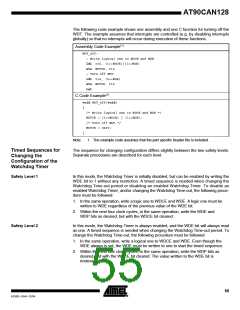
The following code example shows one assembly and one C function for turning off the
WDT. The example assumes that interrupts are controlled (e.g. by disabling interrupts
globally) so that no interrupts will occur during execution of these functions.
Assembly Code Example(1)
WDT_off:
; Write logical one to WDCE and WDE
ldi r16, (1<<WDCE)|(1<<WDE)
sts WDTCR, r16
; Turn off WDT
ldi r16, (0<<WDE)
sts WDTCR, r16
ret
C Code Example(1)
void WDT_off(void)
{
/* Write logical one to WDCE and WDE */
WDTCR = (1<<WDCE) | (1<<WDE);
/* Turn off WDT */
WDTCR = 0x00;
}
Note:
1. The example code assumes that the part specific header file is included.
Timed Sequences for
Changing the
The sequence for changing configuration differs slightly between the two safety levels.
Separate procedures are described for each level.
Configuration of the
Watchdog Timer
Safety Level 1
In this mode, the Watchdog Timer is initially disabled, but can be enabled by writing the
WDE bit to 1 without any restriction. A timed sequence is needed when changing the
Watchdog Time-out period or disabling an enabled Watchdog Timer. To disable an
enabled Watchdog Timer, and/or changing the Watchdog Time-out, the following proce-
dure must be followed:
1. In the same operation, write a logic one to WDCE and WDE. A logic one must be
written to WDE regardless of the previous value of the WDE bit.
2. Within the next four clock cycles, in the same operation, write the WDE and
WDP bits as desired, but with the WDCE bit cleared.
Safety Level 2
In this mode, the Watchdog Timer is always enabled, and the WDE bit will always read
as one. A timed sequence is needed when changing the Watchdog Time-out period. To
change the Watchdog Time-out, the following procedure must be followed:
1. In the same operation, write a logical one to WDCE and WDE. Even though the
WDE always is set, the WDE must be written to one to start the timed sequence.
2. Within the next four clock cycles, in the same operation, write the WDP bits as
desired, but with the WDCE bit cleared. The value written to the WDE bit is
irrelevant.
55
4250E–CAN–12/04

 ATMEL [ ATMEL ]