AT90CAN128
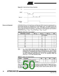
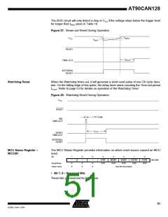
The BOD circuit will only detect a drop in VCC if the voltage stays below the trigger level
for longer than tBOD given in Table 19.
Figure 27. Brown-out Reset During Operation
V
V
BOT+
CC
V
BOT-
RESET
t
TOUT
TIME-OUT
INTERNAL
RESET
Watchdog Reset
When the Watchdog times out, it will generate a short reset pulse of one CK cycle dura-
tion. On the falling edge of this pulse, the delay timer starts counting the Time-out period
tTOUT. Refer to page 53 for details on operation of the Watchdog Timer.
Figure 28. Watchdog Reset During Operation
CC
CK
MCU Status Register –
MCUSR
The MCU Status Register provides information on which reset source caused an MCU
reset.
Bit
7
6
5
4
3
2
1
0
–
–
–
JTRF
R/W
WDRF
R/W
BORF
R/W
EXTRF
R/W
PORF
R/W
MCUSR
Read/Write
Initial Value
R
0
R
0
R
0
See Bit Description
• Bit 7..5 – Reserved Bits
These bits are reserved for future use.
51
4250E–CAN–12/04

 ATMEL [ ATMEL ]