AT90CAN128
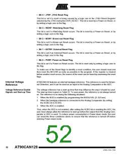
Voltage Reference
Characteristics
Table 22. Internal Voltage Reference Characteristics
Symbol Parameter Condition
VBG Bandgap reference voltage
tBG
Min.
Typ.
1.1
40
Max.
1.2
Units
V
1.0
Bandgap reference start-up time
70
µs
Bandgap reference current
consumption
IBG
15
µA
Watchdog Timer
The Watchdog Timer is clocked from a separate On-chip Oscillator which runs at
1 MHz. This is the typical value at VCC = 5V. See characterization data for typical values
at other VCC levels. By controlling the Watchdog Timer prescaler, the Watchdog Reset
interval can be adjusted as shown in Table 24 on page 54. The WDR – Watchdog Reset
– instruction resets the Watchdog Timer. The Watchdog Timer is also reset when it is
disabled and when a Chip Reset occurs. Eight different clock cycle periods can be
selected to determine the reset period. If the reset period expires without another
Watchdog Reset, the AT90CAN128 resets and executes from the Reset Vector. For tim-
ing details on the Watchdog Reset, refer to Table 24 on page 54.
To prevent unintentional disabling of the Watchdog or unintentional change of time-out
period, two different safety levels are selected by the fuse WDTON as shown in Table
23. Refer to “Timed Sequences for Changing the Configuration of the Watchdog Timer”
on page 55 for details.
Table 23. WDT Configuration as a Function of the Fuse Settings of WDTON
Safety
Level
WDT Initial
State
How to Disable the
WDT
How to Change
Time-out
WDTON
Unprogrammed
Programmed
1
2
Disabled
Enabled
Timed sequence
Always enabled
Timed sequence
Timed sequence
Figure 29. Watchdog Timer
WATCHDOG
OSCILLATOR
~1 MHz
53
4250E–CAN–12/04

 ATMEL [ ATMEL ]