Interrupts
This section describes the specifics of the interrupt handling as performed in
AT90CAN128. For a general explanation of the AVR interrupt handling, refer to “Reset
and Interrupt Handling” on page 13.
Interrupt Vectors in
AT90CAN128
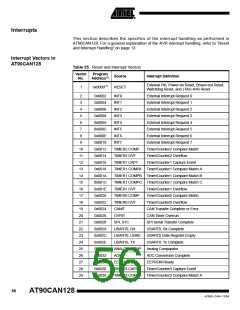
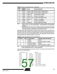
Table 25. Reset and Interrupt Vectors
Vector
No.
Program
Source
Interrupt Definition
Address(2)
External Pin, Power-on Reset, Brown-out Reset,
Watchdog Reset, and JTAG AVR Reset
1
0x0000(1)
RESET
2
0x0002
0x0004
0x0006
0x0008
0x000A
0x000C
0x000E
0x0010
0x0012
0x0014
0x0016
0x0018
0x001A
0x001C
0x001E
0x0020
0x0022
0x0024
0x0026
0x0028
0x002A
0x002C
0x002E
0x0030
0x0032
0x0034
0x0036
0x0038
INT0
External Interrupt Request 0
External Interrupt Request 1
External Interrupt Request 2
External Interrupt Request 3
External Interrupt Request 4
External Interrupt Request 5
External Interrupt Request 6
External Interrupt Request 7
Timer/Counter2 Compare Match
Timer/Counter2 Overflow
3
INT1
4
INT2
5
INT3
6
INT4
7
INT5
8
INT6
9
INT7
10
11
12
13
14
15
16
17
18
19
20
21
22
23
24
25
26
27
28
29
TIMER2 COMP
TIMER2 OVF
TIMER1 CAPT
Timer/Counter1 Capture Event
TIMER1 COMPA Timer/Counter1 Compare Match A
TIMER1 COMPB Timer/Counter1 Compare Match B
TIMER1 COMPC Timer/Counter1 Compare Match C
TIMER1 OVF
TIMER0 COMP
TIMER0 OVF
CANIT
Timer/Counter1 Overflow
Timer/Counter0 Compare Match
Timer/Counter0 Overflow
CAN Transfer Complete or Error
CAN Timer Overrun
OVRIT
SPI, STC
SPI Serial Transfer Complete
USART0, Rx Complete
USART0, RX
USART0, UDRE
USART0, TX
ANALOG COMP
ADC
USART0 Data Register Empty
USART0, Tx Complete
Analog Comparator
ADC Conversion Complete
EEPROM Ready
EE READY
TIMER3 CAPT
Timer/Counter3 Capture Event
TIMER3 COMPA Timer/Counter3 Compare Match A
56
AT90CAN128
4250E–CAN–12/04

 ATMEL [ ATMEL ]