AT90CAN128
...
...
jmp
...
;
0xF00C
SPM_RDY
; Store Program Memory Ready Handler
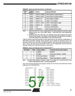
When the BOOTRST Fuse is programmed and the Boot section size set to 8K bytes, the
most typical and general program setup for the Reset and Interrupt Vector Addresses is:
;Address Labels Code
.org 0x0002
Comments
0x0002
0x0004
...
jmp
jmp
...
jmp
EXT_INT0
PCINT0
...
; IRQ0 Handler
; PCINT0 Handler
;
0x002C
;
SPM_RDY
; Store Program Memory Ready Handler
.org 0xF000
0xF000
0xF001
0xF002
RESET: ldi
r16,high(RAMEND) ; Main program start
out
SPH,r16
; Set Stack Pointer to top of RAM
ldi
r16,low(RAMEND)
SPL,r16
0xF003
0xF004
out
sei
; Enable interrupts
0xF005
<instr> xxx
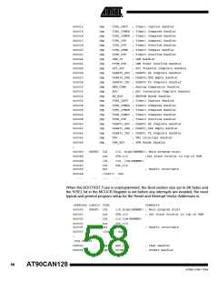
When the BOOTRST Fuse is programmed, the Boot section size set to 8K bytes and the
IVSEL bit in the MCUCR Register is set before any interrupts are enabled, the most typ-
ical and general program setup for the Reset and Interrupt Vector Addresses is:
;Address Labels Code
Comments
;
.org 0xF000
0xF000
0xF002
jmp
jmp
RESET
EXT_INT0
; Reset handler
; IRQ0 Handler
0xF004
...
jmp
...
jmp
PCINT0
...
; PCINT0 Handler
;
0xF044
;
SPM_RDY
; Store Program Memory Ready Handler
0xF046
0xF047
0xF048
RESET: ldi
out
r16,high(RAMEND) ; Main program start
SPH,r16
; Set Stack Pointer to top of RAM
ldi
r16,low(RAMEND)
SPL,r16
0xF049
0xF04A
out
sei
; Enable interrupts
0xF04B
<instr> xxx
Moving Interrupts
Between Application and
Boot Space
The General Interrupt Control Register controls the placement of the Interrupt Vector
table.
MCU Control Register –
MCUCR
Bit
7
6
–
5
–
4
3
–
2
–
1
IVSEL
R/W
0
0
IVCE
R/W
0
JTD
R/W
0
PUD
R/W
0
MCUCR
Read/Write
Initial Value
R
0
R
0
R
0
R
0
59
4250E–CAN–12/04

 ATMEL [ ATMEL ]