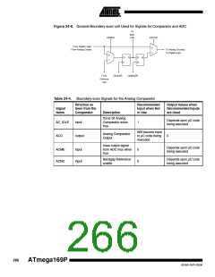
Figure 24-8. General Boundary-scan cell Used for Signals for Comparator and ADC
To
Next
ShiftDR
Cell
EXTEST
From Digital Logic/
From Analog Ciruitry
0
1
To Analog Circuitry/
To Digital Logic
0
1
D
Q
D
G
Q
From
ClockDR
UpdateDR
Previous
Cell
Table 24-4. Boundary-scan Signals for the Analog Comparator
Direction as
Seen from the
Comparator
Recommended
Input when Not
in Use
Output Values when
Recommended Inputs
are Used
Signal
Name
Description
Turns off Analog
Comparator when
true
Depends upon µC code
being executed
AC_IDLE
ACO
input
1
Will become input
to µC code being
executed
Analog Comparator
Output
output
0
Uses output signal
from ADC mux when
true
Depends upon µC code
being executed
ACME
ACBG
input
input
0
0
Bandgap Reference
enable
Depends upon µC code
being executed
266
ATmega169P
8018A–AVR–03/06

 ATMEL [ ATMEL ]