ATmega169P
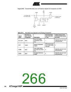
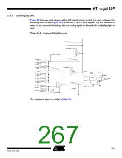
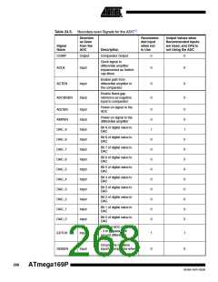
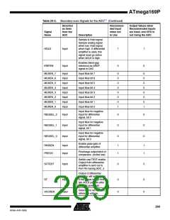
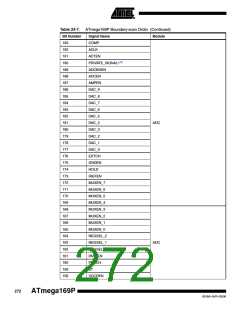
Table 24-5. Boundary-scan Signals for the ADC(1) (Continued)
Direction
as Seen
from the
ADC
Recommen-
ded Input
when not
in Use
Output Values when
Recommended Inputs
are Used, and CPU is
not Using the ADC
Signal
Name
Description
Sample & Hold signal.
Sample analog signal
when low. Hold signal
when high. If differential
amplifier is used, this
signal must go active
when ACLK is high.
HOLD
Input
1
1
Enables Band-gap
reference as AREF
signal to DAC
IREFEN
Input
0
0
MUXEN_7
MUXEN_6
MUXEN_5
MUXEN_4
MUXEN_3
MUXEN_2
MUXEN_1
MUXEN_0
Input
Input
Input
Input
Input
Input
Input
Input
Input Mux bit 7
Input Mux bit 6
Input Mux bit 5
Input Mux bit 4
Input Mux bit 3
Input Mux bit 2
Input Mux bit 1
Input Mux bit 0
0
0
0
0
0
0
0
1
0
0
0
0
0
0
0
1
Input Mux for negative
input for differential
signal, bit 2
NEGSEL_2
NEGSEL_1
NEGSEL_0
Input
Input
Input
0
0
0
0
0
0
Input Mux for negative
input for differential
signal, bit 1
Input Mux for negative
input for differential
signal, bit 0
Enable pass-gate of
differential amplifier.
PASSEN
PRECH
Input
Input
1
1
1
1
Precharge output latch of
comparator. (Active low)
Switch-cap TEST enable.
Output from differential
amplifier is sent out to
Port Pin having ADC_4
SCTEST
Input
0
0
Output of differential
amplifier will settle faster
if this signal is high first
two ACLK periods after
AMPEN goes high.
ST
Input
Input
0
0
0
0
Selects Vcc as the ACC
reference voltage.
VCCREN
269
8018A–AVR–03/06

 ATMEL [ ATMEL ]