AT90PWM2/3/2B/3B
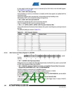
In accordance with the Table 21-6, these 3 bits select the interrupt event which will generate the
trigger of the start of conversion. The start of conversion will be generated by the rising edge of
the selected interrupt flag whether the interrupt is enabled or not. In case of trig on PSCnASY
event, there is no flag. So in this case a conversion will start each time the trig event appears
and the previous conversion is completed
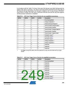
Table 21-6. ADC Auto Trigger Source Selection for non amplified conversions
ADTS3
ADTS2
ADTS1
ADTS0
Description
0
0
0
0
0
0
0
0
1
1
1
1
1
1
1
1
0
0
0
0
1
1
1
1
0
0
0
0
1
1
1
1
0
0
1
1
0
0
1
1
0
0
1
1
0
0
1
1
0
1
0
1
0
1
0
1
0
1
0
1
0
1
0
1
Free Running Mode
Analog Comparator 0
External Interrupt Request 0
Timer/Counter0 Compare Match
Timer/Counter0 Overflow
Timer/Counter1 Compare Match B
Timer/Counter1 Overflow
Timer/Counter1 Capture Event
PSC0ASY Event (1)
PSC1ASY Event(1)
PSC2ASY Event(1)
Analog comparator 1
Analog comparator 2
Reserved
Reserved
Reserved
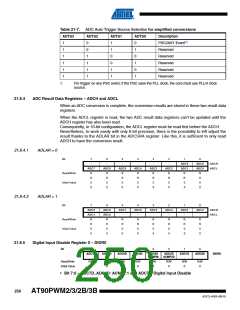
1.
For trigger on any PSC event, if the PSC uses the PLL clock, the core must use PLL/4 clock
source.
Table 21-7. ADC Auto Trigger Source Selection for amplified conversions
ADTS3
ADTS2
ADTS1
ADTS0
Description
Free Running Mode
Reserved
0
0
0
0
0
0
0
0
1
1
0
0
0
0
1
1
1
1
0
0
0
0
1
1
0
0
1
1
0
0
0
1
0
1
0
1
0
1
0
1
Reserved
Reserved
Reserved
Reserved
Reserved
Reserved
PSC0ASY Event (1)
PSC1ASY Event(1)
249
4317J–AVR–08/10

 ATMEL [ ATMEL ]